Synchronization of traces
Introduction
Every recording group refers to exactly one master for synchronization. DeltaT is determined, i.e. the time shift between recording group and master. If the master already has a deltaT (it has been assigned another master as recording group), that deltaT is added to the current shift. The time stamp source has no master. Therefore its deltaT is always 0. All identified deltaT refer to it.
At present there are the following kinds of identification:
Offset: a fixed offset is added to the deltaT of the master
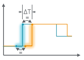
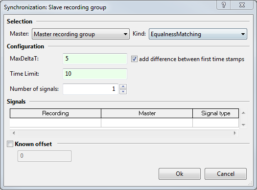
EqualnessMatching : recordings are aligned by means of signals which must have the same value
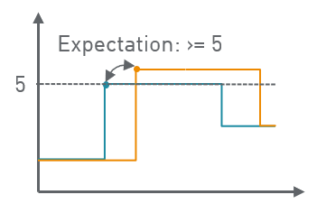
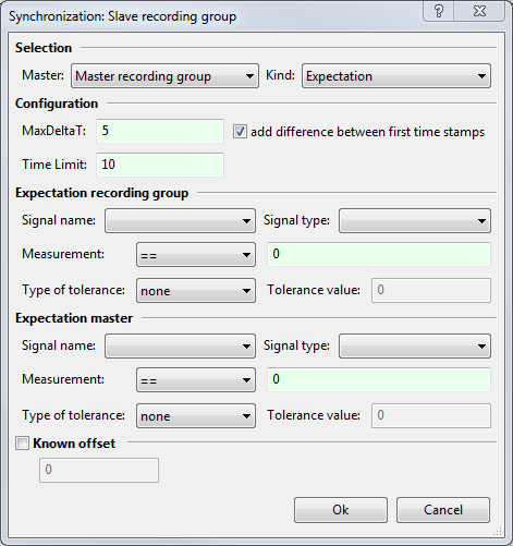
Expectation: an expectation value is specified for both recording group and master. The change of evaluation from false to true determines the point of synchronization.
Nearly all kinds of synchronization have the following parameters:
MaxDeltaT: maximum deltaT
TimeLimit: time passed in the master group after which synchronization is aborted.
The target is to analyze traces of different recording groups along a common time axis.
Initially every trace carries its own time axis. If the traces come from sources with synchronous clocks they can be considered pre-synchronized, and the timestamps of the traces can be used unchanged for trace analysis.
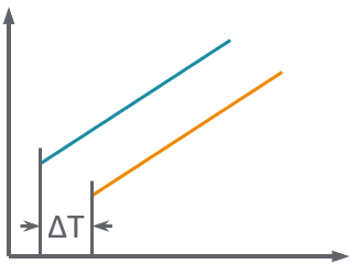
If for technical reasons there are shifts between the clocks of the trace sources, the individual time axes of the traces are shifted against each other. The purpose of synchronization is to realign the time axes of such traces by a value ΔT either known in advance or to be determined.
Subsequently, the value ΔT is automatically added by ecu.test to the time stamps of the traces concerned in order to compensate the original shift of the time axes. ΔT can have both positive and negative values.
ecu.test arranges the traces in recording groups. Synchronization is configured between recording groups and then affects all traces in those recording groups.
Recording groups are synchronized in pairs. The user indicates for two recording groups how ecu.test should calculate the value ΔT for the time shift between traces of both groups.
Procedure
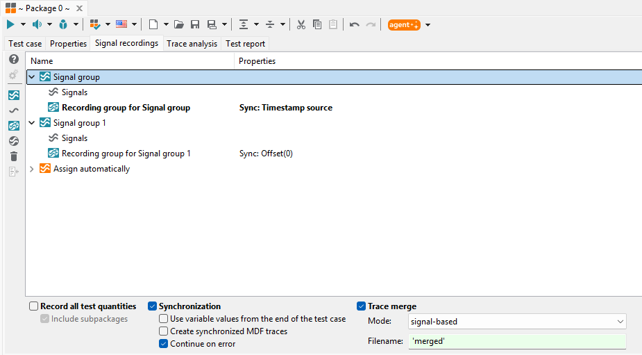
Synchronization is activated by the option field Synchronization.
The recording group whose time stamps should remain unchanged is selected by right-clicking it and selecting Time stamp source in the context menu.
For any other recording group, you can now configure how and against which recording group synchronization should be conducted. To do this, edit the respective recording group (double-click or context menu Edit), and go to the tab Synchronization in the dialog that opens.
The setting Use variable values from the end of the test case determines, whether only the values at the end of the test case should be used for the parametrization of the synchronization. By default, the values are calculated dynamically at run time.
If the option Generate synchronized MDF traces is activated, all MDF traces will be copied to the report directory and their time axes will be adjusted according to the offset Sync delta T determined by the synchronization.
The Continue on error setting can be used to specify whether trace merging and trace analysis should be executed despite an error during synchronization.
Info
Synchronization and trace merge settings can also be configured in a default package being set
in a test configuration (see Default recording configuration). If either a synchronization or a trace merge is
set in the default package of a currently running test configuration, but not in the current
package of the editor, a test configuration icon ( ) will appear to the right
of the respective checkboxes as a remark. Furthermore, if a synchronization is set in the
current package of the editor, but not in the default package, a warning icon (
) will appear to the right
of the respective checkboxes as a remark. Furthermore, if a synchronization is set in the
current package of the editor, but not in the default package, a warning icon ( ) will
appear.
) will
appear.
The tab Synchronization in the Edit dialog comprises the following setting possibilities (with regard to the relative recording group shown in the title bar):
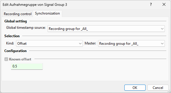
With the option Master in Selection the recording group against which to synchronize can be chosen.
Available kinds of synchronization (with different configuration possibilities in each case) include:
In the following figures the curves depicted in blue always represent the master, whereas the ones depicted in orange represent the signal to be synchronized with respect to the master.
Time limitation parameters
The following parameters can be used in all synchronization methods apart from Offset.
TimeLimit
|
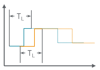
The parameter TimeLimit indicates up to which time stamp (with respect to the start of the trace) the search for a synchronization point should maximally continue. In the figure all values within the range of the solid curves are considered during the synchronization, whereas the values in the range of the dotted curves are ignored. |
MaxDeltaT
|
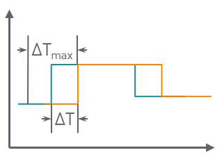
As there may be several possible coincidences, part of which may lead to incorrect causalities, a maximum admissible time shift can be defined by means of the parameter MaxDeltaT with abs(ΔT) <= MaxDeltaT. |
Difference between first time stamps
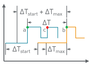
|
If the option add difference between first time stamps is checked, this difference is added to the configured MaxDeltaT. Otherwise exclusively MaxDeltaT is regarded as the maximum admissible time shift. The option is especially usefull under the assumption of identical starting points of the two traces with respect to time. It always applies abs(ΔT) <= MaxDeltaT + abs(ΔTstart). In the figure the unchecked option would lead to the possibly erroneous synchronization between the points (b) and (c), whereas the checked option would lead to the synchronization between points (a) and (b). |
Info
If several possible synchronization points meet the time requirements, the one found first is always used. The time stamps of the master are considered chronologically. At first, it is searched for possible synchronization points in the complete valid time window of the other recordings for one time stamp of the master. Subsequently, the next time stamp of the master is considered.
Offset method
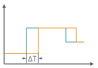
|
|
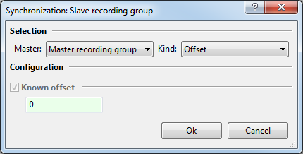
Under Known offset a value ΔT previously known to the user can be set, which will be added to the time stamps of the traces in the recording group to match the time stamps of the other (master) recording group. Negative and positive values can be set. The parameter Known offset can also be set for all other synchronization methods as additional parameter of the time shift, which will be added to the ΔT determined by those methods.
Expectation method
|
|
In this procedure a synchronization point is searched in both traces. In Expectation recording group and Expectation master an expectation is formulated (after Measurement by choosing one of the relations <, <=, ==, !=, >= or > and setting a concrete value) for a signal to be selected (by means of Signal name and Signal type) considering a certain adjustable tolerance (by Type of tolerance and Tolerance value).
Possible synchronization points for each trace are all those time stamps at which the signal changes in such a way that the expectation is fulfilled.
EqualnessMatching method
In all recordings the first time stamp is searched at which all signals to be synchronized have taken a value.
Then the next time stamp is searched in the master where one of those signals changes (that is the first possible synchronization candidate).
All other recordings are searched forward within maxDeltaT until the current synchronization candidate is found.
If that does not work, master is searched for the next time stamp where at least one of the signals to be synchronized has changed.
All other recordings are then searched again.
That is carried on until either a match is found or maxDeltaT is exceeded in the master, too.
|
|
With this method synchronization is made by means of exact value equality of signals without the value being known before.
The prerequisite is that 1 to n signals are present (even with different names) in the two recording groups to be synchronized.
It is searched for a value change to an identical signal value of these signals. The difference between the two time stamps, where the signal values in both traces are identical, is the sought-after value ΔT.
LeastSquares method
|
|
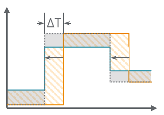
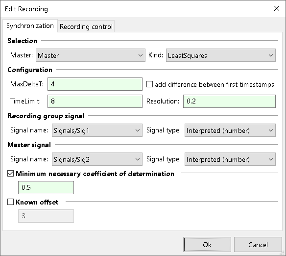
The LeastSquares method determines the time shift that minimizes the sum of the squared differences between two signals (specified by Signal name and Signal type).
The method can be seen as minimization of the area of the envelope created by the difference of both signals (orange ruled to gray filled as depicted in the above figure).
The resolution (or step size) for the shift ΔT is provided by the parameter Resolution. Linear interpolation is used between the existing data points.
Info
If MaxDeltaT is chosen too large, the LeastSquares method tends to minimize the overlap of the signals. Thus, MaxDeltaT should be set to half the size of TimeLimit at most or for recordings that are shorter than TimeLimit, to half the length of the recording. If this is not possible due to a too large shift of the recordings, another synchronization method should usually be selected.
Setting a Minimum necessary coefficient of determination will cause a synchronization to report an error if the signals are not similar enough (i.e. R² is too small). Here, R²=1 symbolizes identical signal behavior while values below one can be interpreted as the shared variance between the two signals. For example, R²=0.25 means that the signals share 25% of their variance.
Info
Despite of the term R², the coefficient of determination may also take on negative values. Negative values state that a constant signal identical to the mean value of the master signal would match the master signal better (R²=0) than the selected signal. Therefore, as a rule, a determination coefficient being at least infinitesimally greater than zero should be selected. Otherwise, the synchronization is implausible for practical applications.
Example
Signal group “Traces_GroupA” contains the signals “SigA_1” and “SigA_2”.
Signal group “Traces_GroupB” contains the signals “SigB_1” and “SigB_3”.
Signal group “Traces_GroupC” contains the signals “SigC_3”, “SigC_4” and “SigC_5”.
The traces of “Traces_GroupA” are to be synchronized with the traces of “Traces_GroupB” by searching a common unique event within signals “SigA_1” and “SigB_1”.
Similarly, the traces of “Traces_GroupB” are to be synchronized with the traces of “Traces_GroupC”, with the time shift between the traces being determined by the signal runs of “SigB_3” and “SigC_3”.
It would be appropriate in this example to use the EqualnessMatching method for synchronization between “Traces_GroupA” and “Traces_GroupB”. For synchronization between “Traces_GroupB” and “Traces_GroupC” either the LeastSquares method (for similar signal behavior) or the Expectation method (for specific relations between the two signals) can be applied.
CrossCorrelation method
|
|
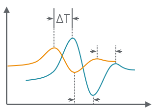
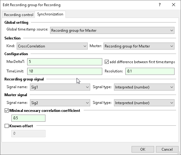
Using the CrossCorrelation method, the similarity between a signal from the master group and a signal from the recording group is determined. The calculation is done by shifting one of the signals by different time shifts (lags) and then determining the correlation coefficient between the two signals, which is the sum of the normalized signal values multiplied in pairs. The lag at which the cross-correlation reaches its maximum value indicates the shift at which the two signals match best.
The resolution (or step size) for the shift ΔT is provided by the parameter Resolution. Linear interpolation is used between the existing data points.
Setting a Minimal necessary correlation coefficient causes a synchronization to report an error if the signals are not similar enough. A correlation coefficient of 1 stands for perfect synchronization, a value of less than 1 indicates what proportion of the variance is shared by both signals. The correlation can also assume negative values. A value of -1 means that the signals to be synchronized are exactly inverse. If the Consider negative correlation option is activated, only the absolute value of the correlation is considered so that positively and negatively correlated signals can be used equally for synchronization.
AUTOSAR Time Synchronization (AutosarTime)
|
|
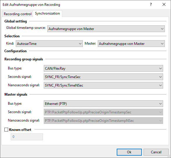
With the Time Synchronization Protocol Specification AUTOSAR provides a possibility, how bus or network nodes can synchronize to a common time base against a master. The standard covers CAN, FlexRay and Ethernet.
For Ethernet, the standard is based on the existing PTP protocol. Therefore, ecu.test automatically determines the required signals. In case of MDF4 buslogging it is necessary to add the pseudo signal PacketPtpFollowUp of the respective ETH bus to the recording group of the master. Regardless of the medium, there are always two integer signals: one for seconds and one for nanoseconds. For CAN and FlexRay special Sync and FollowUp messages are defined. Since these depend on the bus database, the signals for synchronization must be specified explicitly:
CAN: seconds signal SyncTimeSec from PDU SYNC, nanoseconds signal SyncTimeNSec from PDU FUP
FlexRay: signals SyncTimeSec and SyncTimeNSec from the PDU defined in the bus database
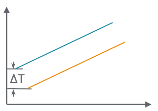
The SyncTimeSec and SyncTimeNSec signals are combined to form the exact time stamps. The shift ΔT of the synchronization corresponds to the difference of the first samples from recording and master.
It is still possible to add a known offset to the shift.
UtcTimestamp time synchronization
|
|
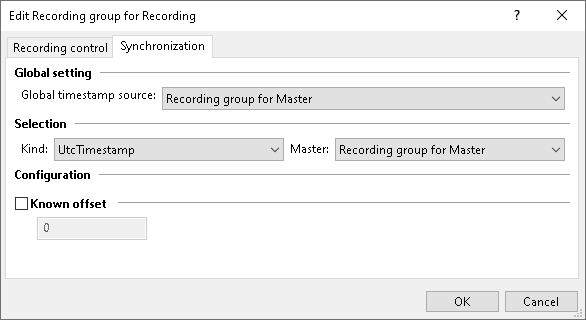
When using the UtcTimestamp synchronization for supported formats (see below) the meta data from the files is read to determine a possible UTC timestamp as a starting point. The difference in timestamps between the master and recording then is the ΔT.
Supported Formats:
Custom synchronization
If the synchronization methods provided in ecu.test are not sufficient, a custom synchronization can be implemented.
A complete description of all relevant methods and interfaces can be found in the Trace Analysis API documentation.
An implementation of this interface is stored as a Python module in the directory for User Python libraries. The custom synchronization is available separately from the built-in methods.
The Time limitation parameters MaxDeltaT` and TimeLimit` are available for all custom synchronizations.
Additional parameters as well as the available signals depend on the specific implementation and are listed in the dialog for parameterization.