Create a triggered analysis
In this tutorial it is shown how an analysis, in this case a calculation step, is executed only if a beforehand defined condition, the trigger, is fulfilled. It is to be checked that the engine speed remains within the upper bound of 6000 RPM while the vehicle is in the 2nd gear. This can be achieved by utilizing a trigger block, which defines the condition for the execution of its subelements, in this case the calculation step. We proceed from the state of “Package 1” after successfully finishing the tutorial Creating a simple trace analysis.
First, go to the tab Signal recordings and insert the two additional signals “EngSpeed”
and “Gear” from the trace file testlauf.mdf via drag-and-drop to the signals of the signal
group “device” (see figure
Inserting signals “EngSpeed” and “Gear” via drag-and-drop).

Inserting signals “EngSpeed” and “Gear” via drag-and-drop
For both signals to be accessible during the trace analysis, two additional generic signals have
to be added in the section Signal connection of the tab Trace analysis by
clicking the button  (New generic signal). The generic signals are
assigned to signals from the signal group “device” in column Recording group signal
(see figure Inserting further generic signals to connect the signals of the signal group “device”).
(New generic signal). The generic signals are
assigned to signals from the signal group “device” in column Recording group signal
(see figure Inserting further generic signals to connect the signals of the signal group “device”).

Inserting further generic signals to connect the signals of the signal group “device”
To improve clearity, set meaningful names identical to those in the trace file for the generic signals. This can be done by clicking twice into the name field in column Generic signal and entering new names (see figure Renaming the generic signals).

Renaming the generic signals
Now both signals are usable by the trace analysis and this can be refined. This time, the existing
calculation step is only to be executed when a certain state of the system has been reached.
Exemplarily it shall be checked that the engine speed in a given gear does not exceed a predefined
upper limit. This can be achieved by utilizing a trigger block ( ). By
right-clicking the trace step calculation in the section Episodes and trace steps a
context menu opens (see figure Inserting a trigger block via the context menu of the calculation step).
). By
right-clicking the trace step calculation in the section Episodes and trace steps a
context menu opens (see figure Inserting a trigger block via the context menu of the calculation step).

Inserting a trigger block via the context menu of the calculation step
Picking the option Insert selection in new trigger block places a trigger block one level above the calculation step and opens up its configuration dialog. The trigger condition is set in the field Start trigger. A click in this field with subsequent pressing the down arrow key opens a list of accessible (= connected) signals as well as various ready-made auxiliary functions, which can simplify the creation of a condition (see figure Choosing available signals and auxiliary functions for defining the start trigger).

Choosing available signals and auxiliary functions for defining the start trigger
Select the signal “Gear” via double-clicking on it and it will be inserted into the expression. Complete the expression by adding “ == 2”. Further adjustment of the trigger block is not necessary in this tutorial. The dialog should finally appear as follows:

Parameterizing a trigger block
Confirm and close the dialog of the trigger block by clicking OK. Next, the expression in the calculation step has to be adjusted (see section Creating a simple trace analysis). Open the configuration dialog of the calculation step by double-clicking on it and replace the comparison “CarSpeed <= 75” in Expression with “EngSpeed < 6000”.
To visualize the results of the analysis, the plot still has to be adjusted. Open its configuration dialog by double-clicking on the trace step Plot in the section Episodes and trace steps. Move the signal “CarSpeed” via drag-and-drop from the category Upper plot to Separate plots, next “Gear” to the first position in Separate plots and finally “EngSpeed” to Upper plot (see figure Adjusting the plot). Apply your settings by clicking OK.
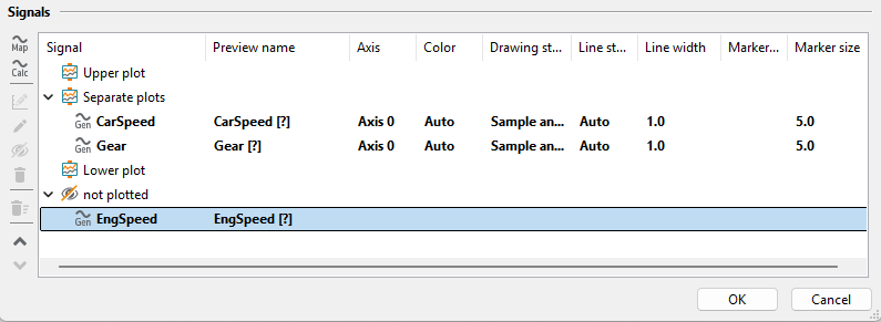
Adjusting the plot
After the execution of the trace analysis its results will be displayed in the tab Test report. Navigate in the report tree to the calculation step. If it is selected, details of its execution will be displayed in the window on the right-hand side.
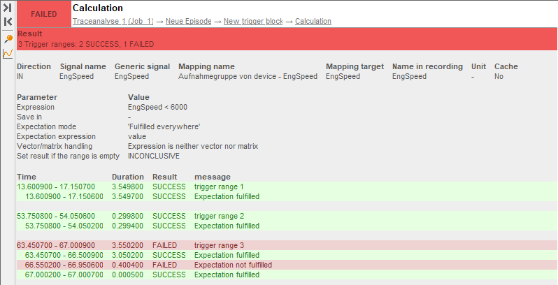
Display of the results of the calculation step
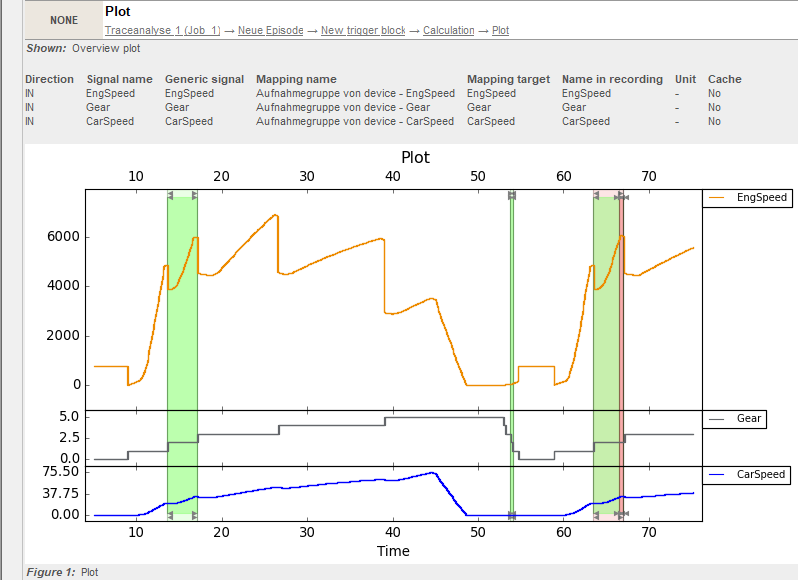
Visualization of the results of the triggered analysis
The following key results can be extracted from the report:
The trigger is true within three time intervals, i.e. in those cases the vehicle was in gear 2.
Between 13.600900 and 17.150700 as well as between 53.750800 and 54.050600 the engine speed remained within the upper bound. Thus, both sections have been rated SUCCESS.
Whereas at the end of the third section between 66.550200 and 66.950600, the maximum engine speed of 6000 RPM was exceeded, which gives the trace analysis the rating FAILED.
Info
Instead of explicitly inserting the upper bound in the trigger block, it is also possible to use the name of a package variable for a more generic analysis.
Detailed description of the trace step trigger block
The section Trigger blocks presents further possible configurations of trigger blocks. For example, the validity of the trigger block can be customized by defining a stop trigger, the analysis can only be performed on the first trigger, or a maximum number of trigger events can be specified.