Signal Segments
A segment is the smallest unit that describes the signal form completely for a defined time period. Each signal segment has specific properties, which are explained in more detail below.
Most of the segments have the property stop trigger. This property is used to end a segment in dependence on other input signals. For more information see stop trigger.
Any other property of simple signal segments can have an expression according to the ASAM COMMON GES (Global Expression Syntax) as a value (see also Data types and file format). More complex segments are the Operation-, Loop-, SignalValue- and DataFileSegments.
Constant segment
For a constant segment the Duration and value (Value) are indicated.
The signal takes the indicated value for the indicated duration.

Within the stimulus test step a constant segment is defined as followed:
ConstantSegment(duration=1.0, value=0.0)
Ramp segment (with start and stop value)
For this kind of segment a Duration, a start value (Start) and a stop value (Stop) are indicated.
The signal rises or falls linearly throughout the indicated duration from start to stop value.

Within the stimulus test step a ramp segment is defined as followed:
RampSegment(duration=1.0, start=0.0, stop=1.0)
Ramp slope segment
For a ramp slope segment the Duration, Offset and slope (Slope) are indicated.
The signal rises (or falls if the slope is negative) throughout the indicated duration from the start value with the indicated slope.

Within the stimulus test step a ramp slope segment is defined as followed:
RampSlopeSegment(duration=1.0, offset=0.0, slope=1.0)
Saw segment
For a saw segment the Duration, Offset, Amplitude, period (Period), slope relation (DutyCycle) and phase position (Phase) are indicated.
The basic signal begins with the start value configured as offset and rises for the duration of (DutyCycle * Period) like a ramp segment to the value (Offset + Amplitude). Then it falls for the duration of ((1 - DutyCycle) * Period) like a ramp segment to the value Offset. That basic signal is repeated periodically.
The signal finally produced corresponds to a section of the basic signal which begins at point (Phase * Period) and ends at point (Phase * Period + Duration).

Within the stimulus test step a saw segment is defined as followed:
SawSegment(duration=1.0, offset=0.0, amplitude=1.0, period=1.0, dutyCycle=0.5, phase=0.0)
Pulse segment
For a pulse segment the Duration, Offset, Amplitude, upper part (DutyCycle) and phase position (Phase) are indicated.
The basic signal begins with the value (Offset + Amplitude) and remains constant for the duration of (DutyCycle * Period). Then it changes to the value Offset and remains constant for the duration of ((1 - DutyCycle) * Period). That basic signal is repeated periodically.
The signal finally produced corresponds to a section of the basic signal which begins at point (Phase * Period) and ends at point (Phase * Period + Duration).
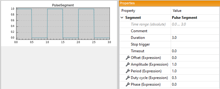
Within the stimulus test step a pulse segment is defined as followed:
PulseSegment(duration=1.0, offset=0.0, amplitude=1.0, period=1.0, dutyCycle=0.5, phase=0.0)
Exponential segment
For an exponential segment the Duration, start value (Start), stop value (Stop) and time constant (Tau) are indicated.
The signal approaches the stop value exponentially according to the formula.

with t starting from 0 at the beginning of the segment.
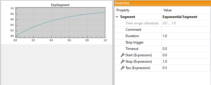
Within the stimulus test step an exponential segment is defined as followed:
ExponentialSegment(duration=1.0, start=0.0, stop=1.0, tau=0.5)
Sine segment
For a sine segment the Duration, Offset, Amplitude, periode (Period) and phase position (Phase) are indicated.
The signal corresponds to a sine curve with the indicated parameters.

Within the stimulus test step a sine segment is defined as followed:
SineSegment(duration=1.0, offset=0.0, amplitude=1.0, period=1.0, phase=0.0)
Empty segment
For an empty segment only a Duration is indicated. For the indicated duration the signal has no value.

Within the stimulus test step an empty segment is defined as followed:
IdleSegment(duration=1.0)
Noise segment
For a noise segment the Duration, Mean, standard deviation (Sigma) and a Seed value for the random number generator are indicated.
The signal takes a random value at each scanned point for the indicated duration. The values correspond to a normal distribution with the indicated standard deviation. With the same Seed the noise always has the same form.
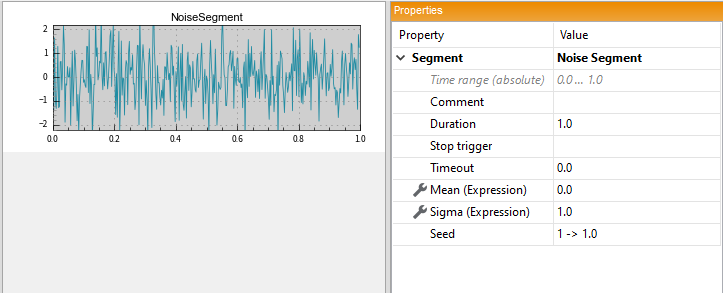
Within the stimulus test step a noise segment is defined as followed:
NoiseSegment(duration=1.0, mean=0.0, seed=1, sigma=1.0)
SignalValue Segment
The SignalValueSegment makes it possible to directly enter timestamps and values.

In order to create a continuous signal, an Interpolation mode must be provided. Have a look at the Properties for further information.
Within the stimulus test step a signal value segment is defined as followed:
SignalValueSegment(timeVector=[0.0, 0.1, 0.2, 0.3], dataVector=[0, 1, 2, 3], interpolationType='backward')
In order to save SignalValues appropriately a ‘.mat’ file is created tat contains the time- and valuevector. To be sure that the ‘.mat’ files are always available, the stimulation file should be saved as an ‘.stz’ file (see Data types and file format).
Attention: If the timestamps of the segment do not start with the timestamp 0.0 the timestamps get shifted such that the first timestamp is equal to 0.0.
Using the Signal Editor the timestamps-value-table of the SignalValueSegment can be filled comfortably in different ways. One possibility is to use the context menu of the workspace tree to convert any segment into a SignalValueSegment. Therefore a sample rate must be specified that is used to generate the timestamps and values. Another way is to use an excel document to import some data. The data must be in two columns and is only allowed to contain numerical values. In order to transfer the data from excel to the SignalValueSegment, copy the data in excel and paste it into an empty cell of the value-table of the SignalValueSegment.
DataFile Segment
The DataFileSegment makes it possible to reference another file containins some data. Therefore the properties FileName, Time signal and Data Signal need to be set.
The referenced file can be of any trace format that is supported by ecu.test, whereby there can be limitations of the tool to be stimulated with regard to the supported file formats. The file formats MAT and MF4 are mostly compatible and therefore to be preferred if possible.
A suitable MAT file can be generated, for example, with the MATLAB tool as follows:
time = [0.0, 0.1, 0.2, 0.3];
data = [1, 2, 3, 4];
save('stimulus.mat', 'time', 'data', '-v6');
The saved path (FileName) will be a relative path from the ‘.sti’ (‘.stz’) file to the referenced file. When moving or copying the stimulation file around, make sure that the referenced files are still available.
The referenced files contain signal values consisting of a timestamp and a value. In order to create a continuous signal, an Interpolation mode must be provided. Have a look at the Properties for further information.
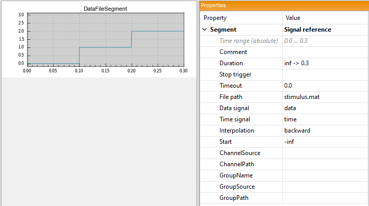
Within the stimulus test step a data file segment is defined as followed:
DataFileSegment(filePath='path/to/datafile', timeVectorName='time', dataVectorName='signal', interpolationType='backward')
The properties Duration and Start are set to inf and -inf respectively per default. These settings will replay the whole signal of the referenced file.
If not all values of the referenced file should be used, the Start and/or Duration property can be set. Setting the Start property to an explicit value will start the signal at this timestamp. Otherwise the signal is started from the first timestamp found in the referenced file. Analogical the signal is played until the last timestamp found in the referenced signal, except the Duration property is set to an explicit value.
Attention: the range resulting from the properties Start and Duration has to be valid with respect to the range resulting from the first and last timestamp found in the referenced file.
As with the SignalValueSegment the timestamps of the resulting signal get shifted such that the first timestamp is corresponding to 0.0.
Additionally to the already described properties there exist the following attributed, which are especially relevant when using referenced MF4 files. A specific selection in these properties will filter the available signals and thus reduces the number of elements visible at data signal.
ChannelSource : The channel source typically contains the network node name or the task name.
ChannelPath : The channel path typically contains the device name or platform name.
GroupName : The group name typically contains the task name, the raster name or the event name.
GroupSource : The group source typically contains the network node name, the tool name or the task name.
GroupPath : The group path typically contains the device name or platform name.
Operation Segment
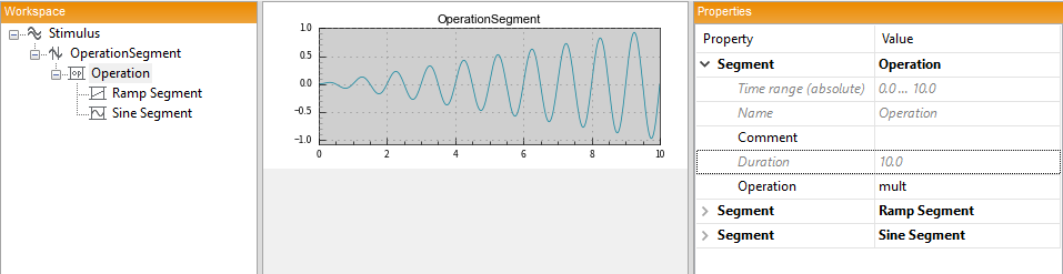
For a segment defined by linking of two segments the required Operation (addition add or multiplication mult) are indicated and the segments to be linked are added by means of the icons in the toolbar. The duration results automatically from the shortest duration of the segments to be linked.
It is also possible to use a segment defined by linking as segment to be linked, i.e. nesting the operations.
Loop Segment
When parts of a signal shall be repeated, a loop segment can be used. For example it is possible to define a trapezoid (ramp slope - constant - ramp slope) thas is repeated several times.
