Signal Editor
The Signal Editor permits to create simple and complex signal patterns that can be integrated into ecu.test as stimuli. A stimulus is a signal which can be applied on models or model parts. The model read steps permit a tool which allows to prove in a test case if the model behaves as desired.
Additionally, the signal patterns that are created with the Signal Editor can be used as reference traces in trace analysis scenarios. Chapter Using graphically modeled reference signals gives a brief introduction on how to accomplish this.
The Signal Editor can be started by clicking . In the following points the assembly and functionality of the Signal Editor will be described.

The window of the Signal Editor is divided into four parts. On the upper edge there are the menu and toolbars, that provide basic functionalities for editing the stimulation file. The main area is divided into three parts. On the left side there is the workspace tree and the parameter table. The workspace tree provides an overview on the structure of the stimulation file. The parameter table displays currently used parameters of the stimulation file. The biggest view is placed in the middle of the screen and is called the signal board. There you can see all the existing signals of the stimulation file. On the right side the property area is placed. The property area provides information about currently selected signals or segments and allows to edit them.
Signals can be described in two possible ways:
segment signal descriptions describe the signal wave by combining multiple signal segments, and
operation signal descriptions that operate (addition or multiplication) on segment signal descriptions.
Menu and Toolbar

There are two toolbars. The first one contains the following standard functionalities starting on the left:
create a new file
open an existing file
Save
Save as
Export to CSV
Cut
Copy
Paste
Delete
Undo
Redo
Additionally the toolbar contains the following functionalities to edit the stimulation file:
Add constant segment
Add saw segment
Add pulse segment
Add sine segment
Add empty segment
Add noise segment
Add loop segment
The second toolbar provides functionalities to customize the view:
Show/Hide the cursor
Show/Hide the common timeaxis
Show/Hide grid
In-/Decrease the view of a signal
Automatically adjust the size of signal views to fit the window
Reset the shows signal range
Duration of the shown signal range
Settings for the sample rate
If an icon is enabled or disabled depends on the element selection in the workspace tree. A chosen toolbar action always effects the currently chosen element.
Besides all described funcitonalities the menu bar provides an additional feature. In the menu at there are three possible positions:
centrally above the signals view,
in the upper right corner of the signals view, or
no signalname position.
Signal board
The signal board contains a graphical representation of the signals of the stimulation file. The signal views can be adjusted using the tools provided by the second toolbar. The order of the signals can be changed using Drag and Drop in the workspace tree.
Workspace
The workspace displays the structured tree representation of the stimulation file.
A signal description or signal segment can be selected by left click. The chosen element gets highlighted in the signal board. The properties of the chosen element get displayed in the property area and can be manipulated.
Clicking right on an element of the workspace opens a context menu that provides additional functionalities besides the also in the toolbar provided ones. Signal descriptions as well as signal segment can be moved around using Drag and Drop in the workspace. Signal segments can also be moved between different segment signal descriptions. Pressing Ctrl during the process of Dragging will copy the element to its new position.
Contextmenu of a workspace element
The contextmenu provides additional functionalities to the also in the toolbar provided ones. These are amongst others:
replacing a segment with another one
This function facilitates the replacement of one segment with another. The duration of the segment to be repaced will be copied to the new one, keeping the over all duration of the signal description. Attention: If the new segment is an Operation-, loop-, SignalValue- or DataFileSegment the duration can not be copied, since the duration of these segments depends on their content and cannot be set explicitly.
embedding a segment in an Operation- or loopSegment
This function facilitates the embedding of a segment into an Operation- or loopSegment. It’s easy to modify or repeat the chosen element.
converting a segment into a SignalValueSegment
This function facilitates the generation of timestamp-value-pairs that are needed to fill a SignalValueSegment. During the conversion a sample rate can be provided in order to specify how many timestamps should be generated.
Segment signal description
A segment signal description is the combination of multiple signal segments describing a signal wave.
By clicking the corresponding icon in the toolbar a segment signal description is created. If the signal description is selected the properties (such as name) can be modified in the property area. By clicking the icon of a signal segment it gets added to the segment signal description. The order of the signal segments correspond to the wave the signal will represent.
The duration of a signal description is the sum of all duration of its signal segments.
The different kinds of signal segments are described in more detail in the following chapters:
Operation signal description
As well as a segment signal description an operation signal description is created by clicking the corresponding icon in the toolbar. If the newly created operation signal description is selected the properties can be modified.
An operation signal description operates on exactly two other signal descriptions. The operands can be chosen in the property area by setting the property Left signal name and Right signal name. In order to perform operations with more than two other signal descriptions operation signal descriptions itself can contain other operation signal descriptions. Attention: it is not allowed to create cycles.
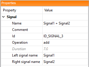
Alternatively the addition or deletion of signal descriptions as operands can be done using the context menu of the element.
The duration of a signal results from the minimum lengths of its operands.
Data types and file format
The file format for stimulation files are based on the ASAM HIL 1.0 and XIL 2.0/2.1/2.2 standard respectively. Using the Signal Editor it is possible to create and save .sti and .stz files based on the ASAM XIL 2.0/2.1/2.2 format. Files based on the older standard HIL 1.0 can be opened but get transformed to XIL 2.0 immediately. The extension ‘.sti’ is derived from the word ‘stimulation’. An ‘.stz’ file is a compressed ‘.sti’ that also contains possibly needed ‘.mat’ files if SignalValueSegments are used.
The used data types for properties of signal descriptions and signal segments differ depending on the used standard version.
ASAM HIL 1.0- and XIL 2.0 Format
The most properties of signal descriptions and signal segments use floating point values. Exceptions are names, commentaries and stop trigger expressions.
XIL 2.1/2.2 Format
If the stimulation file is saved in versions 2.1 or 2.2 the floating point values are replaced by expressions according to the ASAM COMMON GES (Global Expression Syntax). ASAM COMMON GES defines comparative operations that are only allowed in stop trigger expressions. Additionally parameters can be used in the expressions. Used parameters are managed in the parameter table.
Stop trigger

Almost all segments can contain stop triggers. With these it is possible to play a signal dependent on the values of another signal. Using expressions, the user can set a threshold at which the play-back of the current segment should be stopped and the playback of the next segment should be started. The expressions are defined using a subset of the ASAM COMMON GES. The expression can contain input signal names as variables that will be evaluated at runtime. Additionally a timeout (in seconds) can be set, at which the play-back of the current segment will stop immediately.
Input signal
Input signals are variables that are defined in the .sti file. They can be used in stop trigger expressions and will be evaluated at runtime. Input signals can also be used in selected properties of signal segments to influence them dynamically at runtime. The specified input signals can then be linked to suitable mappings in the Start Stimulus. The possibility of using input signals is not available with all tools, however.
Table of parameters
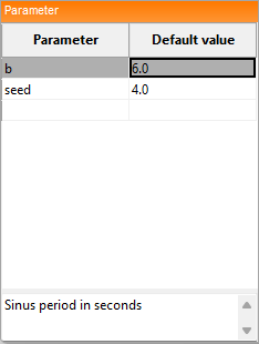
The table of parameters managed parameters that are used in the stimulation file. It is possible to set values for each parameter. The last row of the table is an empty row and can be used to add parameters directly in the table of parameters. Selecting a row and pressing DEL on the keyboard removes the selected parameter. Parameter show in the table of parameters can be used in the property expressions in the property area. Optionally parameters can have a description that is displayed below the table.
Attention: If parameters are used, the stimulation file can only be saved in the formats XIL 2.1 and 2.2..
Cursor
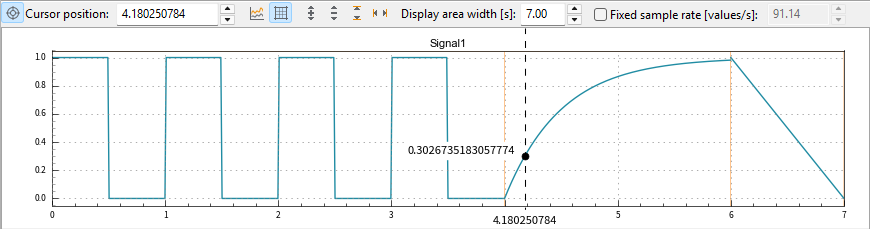
Pressing the key C on the keyboard or clicking (and holding) right displays a cursor in the signal board. Holding the right mousekey or setting the wanted position in the textfield Cursor Position of the toolbar sets the position of the cursor. Pressing the key C again or clicking the marked icon in the toolbar hides the cursor.
Attention: the cursor always snaps to real samples that are calculated according to the sample rate.
Common timeaxis

Clicking the icon common timexis in the toolbar hides the timeaxis of signal views except the last one. This creates more space to view the signals. In the example figure additionally the option, signal name in the top right corner of the signals view, is chosen via ‘ to create even more space.
Sample rate

The calculation of the signal views is based on the given sample rate, set in the toolbar. For each toolbar and signal a timestamp and corresponding value is calculated and shown in the signals view. The sample rate can be set to two different modes:
dynamic sample rate, and
static fixed samplerate.
The dynamic sample rate gets adjusted depending on the shown signal range and the width of the window such that each for each pixel a value is calculated. For fixed static sample rate the shown signal range or the width of the window are irrelevant. The example shows 50 values per second independendly of the shown signal range or window width.