Lesson 2: Test configuration and test bench configuration
In this lesson, you learn the two central configurations in ecu.test and set them up for an example model access. This gives you the foundation you need to create test cases in the following exercises that access real-world test data.
At the end of this exercise, you have created, loaded, and started a test bench configuration and a test configuration using the Test bench configuration editor and the Test configuration editor. You can also access the model quantities of an example system.
Prerequisites:
Lesson 1 is completed.
ecu.test is started with the Tutorial workspace.
The two configurations in ecu.test
As soon as a test case no longer performs only simple calculations but accesses real test quantities, additional information is required. You need to know which test quantities are available for the test and which tool is used to access these quantities.
This information is intentionally split into two configuration types:
- Test bench configuration (TBC)
Describes the technical test environment, including hosts, tools, and ports, and provides technical access to the test quantities.
- Test configuration (TCF)
Describes the System under test (SUT) and its data sources, such as models, ECU descriptions, or bus databases. It provides the functional view and makes the test quantities available.
This separation has the advantage that the test bench and the SUT can be adapted or replaced independently. A test case can therefore be reused in different phases (for example SiL and HiL).
Executable test cases always require the combination of TBC and TCF. If both configurations are available and loaded in ecu.test, the required test quantities of the test system and the SUT can be accessed.
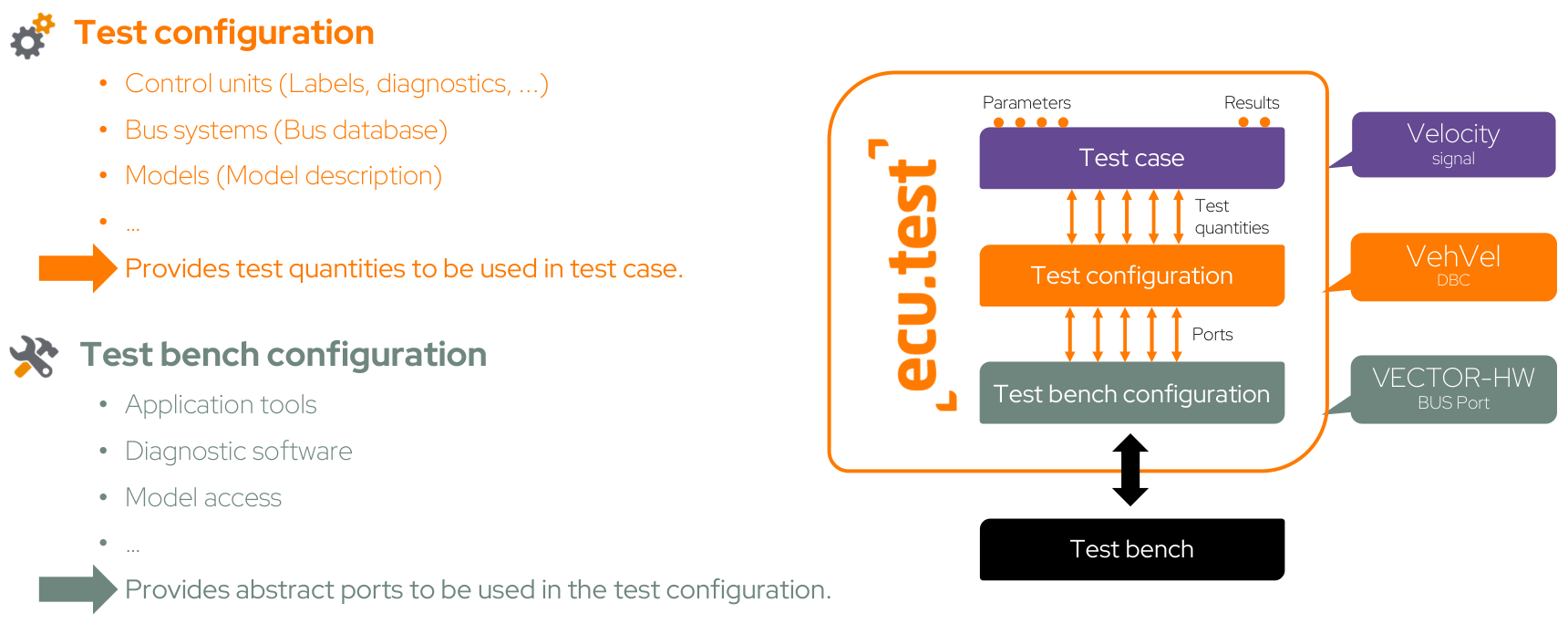
Configuration of test objects within the test bench
Info
In addition to system and tool access, the test configuration’s temporal behaviour also influences test execution. On the Execution tab, you define whether a test case runs in real time or in simulation time and whether the simulation progresses stepwise or continuously.
Terms of the test bench configuration
- Host
The computer on which a tool is executed, locally or remotely.
- Tool
A supported tool that enables access to interfaces or test quantities.
- Port
The abstract interface through which access is used in ecu.test.
Info
In practice, it helps to think of tool and port via the corresponding category:
In this lesson, you use Model access with FMI and port type
MODELACCESS.The same pattern later applies to Application access (e.g. INCA, CANape), Diagnostics, Bus communication, or Service access.
For an overview of all categories, see Tool categories.
Info
For background on tool interfaces (ToolLibs), local and remote connectivity via Tool Server, and advanced configuration in ToolLibs.ini, see Tool interfaces.
The test configuration provides the functional description of the test quantities. The test bench configuration provides technical access via tools and ports. Test cases contain the test logic and utilize both combined, as illustrated here for SiL and HiL:
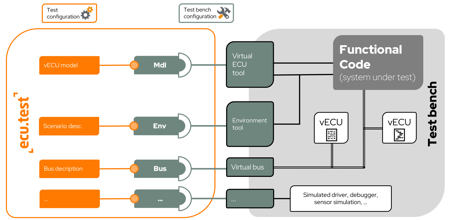
“System under test” and test bench in SiL context.
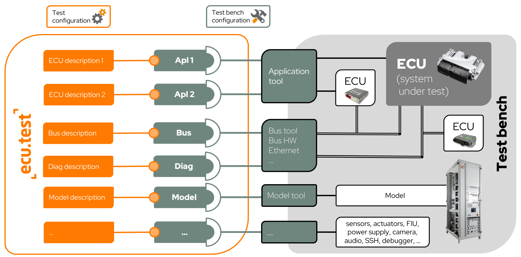
“System under test” and test bench in HiL context.
Different file formats are used as the basis in each port, i.e. in each functional domain.
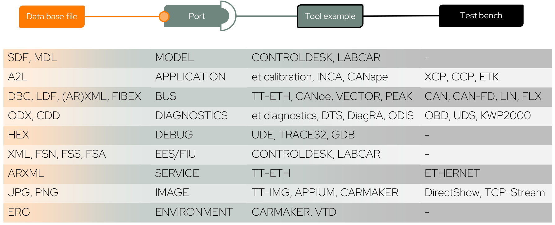
Common file formats per port and tool and how they relate to each other.
Create test bench configuration and test configuration
In this exercise, you create both configurations and load them in ecu.test. After that, access to the configured system is available.
Since no real test system is available, the FMI tool from the Modelica Association is used. It accesses a sample model stored in the training workspace. No external tool is required.
Create a test bench configuration
The test bench configuration provides technical access. You create a tool host and a port for the FMI tool.
To use a tool, a matching tool host is required. In this example, you are working locally. Therefore, ecu.test creates a local tool host automatically.
Select .
In the Test bench configuration editor, the available tools are shown.
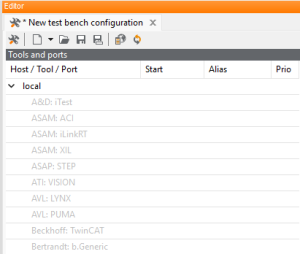
Right-click Modelica Association: FMI and select New Port.
Select port type
MODELACCESSand confirm with OK.Below the tool, the entry MDL01 (MODELACCESS) is displayed. This provides model access via the test bench configuration.
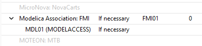
Save the TBC (shortcut Ctrl+S).
The file explorer opens in the
Configurationsdirectory of the configured workspace.Enter a name (for example
FMI.tbc).Confirm with Save.
The TBC appears in the ecu.test workspace explorer under
Configurationsand can be opened and edited again from there.Load the test bench configuration by clicking the tool icon.
Alternative: Drag and drop the TBC file from the workspace explorer into the Configurations area.
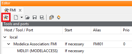
The newly created TBC is loaded and displayed in the Configurations area.

Close the TBC editor by clicking the X in the tab.
Create a test configuration
The test configuration describes the test object. You add a model file so that the model quantities of the system become available in ecu.test.
Select .
Switch to the Platform tab.
Right-click Model Access and select New.
Select any value as system name and confirm with OK.
Select model port MDL01.
In the Model field, use Choose file to select the provided file
Offline-Models/EV_SIL.py.This registers the data source for the system. The contained model quantities are loaded later and can be used in test cases.
Save the TCF (shortcut Ctrl+S).
The file explorer opens in the
Configurationsdirectory of the configured workspace.Enter a name (for example
EV_SIL.tcf).Confirm with Save.
The TCF appears in the ecu.test workspace explorer under
Configurationsand can be opened and edited again from there.Load the TCF by clicking the gear icon.
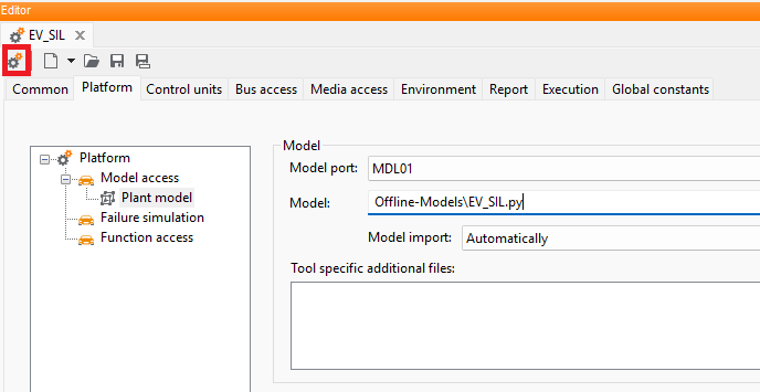
Alternative: Drag and drop the TCF file from the workspace explorer into the Configurations area.
The newly created TCF is loaded and displayed in the Configurations area.
Close the TCF editor by clicking the X in the tab.
Load and start both configurations
After saving, both configurations are located in the Configurations folder in the
workspace explorer. If they were already loaded via the Editor, steps 1 and 2 are not
relevant and you start with step 3.
Otherwise, load the configurations from the workspace explorer into the Configurations window:
Right-click the TBC file in the workspace explorer and select Select test bench configuration.
Right-click the TCF file in the workspace explorer and select Select test configuration.
Both configurations are displayed in the Configurations window.
In the Configurations window, click the play button.
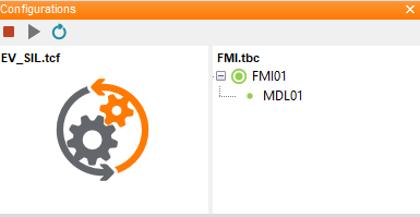
The configurations are loaded, the model file is read, and the connection to the FMI model is established. Green dots on tool and port indicate successful loading. The Model Access tab is additionally available in the action window.
In addition, configuration-dependent content becomes available, for example:
further tool-dependent tabs in the action window
tool-specific jobs
resolved global constants and mapping references
Verify access to the system in ecu.test
After loading, the model quantities of the system are visible in ecu.test. Check whether they are available in the Model Access tab under the selected system name.
In the action window, open the Model Access tab.
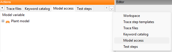
Expand the root node (The root node name corresponds to the selected system name in the TCF.).
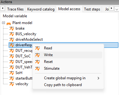
All test system quantities are displayed. If a package is open and active in the editor, you can insert these quantities directly as test steps.
Result of lesson 2
You have created, loaded, and started a test bench configuration and a test configuration. Model access is visible in ecu.test, and the available system quantities are ready for further use in test cases.
Access to other ports such as application, diagnostics, or multimedia works according to the same principle but is not part of this introduction.
In the next exercise, you use the now available test quantities in a test case and access them in read and write mode via the configured tool.
Continue with Lesson 3.