Modelica Association: FMI
Vendor information
Vendor |
Web page |
Product name |
Version |
|---|---|---|---|
Modelica Association |
Functional Mock-up Interface |
1.0, 2.0, 3.0 |
Categories
MDL 🛈 |
APL 🛈 |
BAN 🛈 |
BMA 🛈 |
SVC 🛈 |
DGN 🛈 |
FIU 🛈 |
EES 🛈 |
FCT 🛈 |
DBG 🛈 |
IMG 🛈 |
AUDIO 🛈 |
ENVSIM 🛈 |
ENVCOM 🛈 |
|---|---|---|---|---|---|---|---|---|---|---|---|---|---|
✓ |
✓ |
✓ |
✓ |
Platform
Operating system |
Support |
|---|---|
Windows |
✓ |
Linux |
✓ |
Ports
Specifics
The Functional Mock-up Interface (FMI standard) is a standard for the exchange and simulation of Functional Mock-up Units (FMUs). With ecu.test FMUs can be tested and validated.
FMU simulation with ecu.test
For simulating FMUs, ecu.test uses the FMPy library. Both 64-bit and 32-bit FMUs are supported. To use 32-bit FMUs, a 64-bit wrapper is required, which can be added via the FMPy GUI.
Steps to integrate 32-bit FMUs:
Install FMPy and start the FMPy GUI.
Open the 32-bit FMU: File > Open
Add the 64-bit wrapper: Tool > Add Remoting > Windows 32-bit on Windows 64-bit
Info
For “ModelExchange” FMUs the solver “CVode” from FMPy is used by default.
Simulation model configuration
As model file either an FMU (*.fmu) or a PythonFMU compatible Python file (*.py) can be used. For Python files ecu.test automatically generates a temporary PythonFMU when starting the configuration.
Access to signals and parameters
With ecu.test signals and parameters of an FMU can be read, written, and recorded. Stimulation of scalar test quantities is also possible.
Info
Limitations:
Test quantities with more than 2 dimensions are not supported.
“Clock” signals (from FMI 3.0) are not shown in the model access tab. They are only used internally for communication according to Layered Standard for Network Communication (FMI-LS-BUS).
“structuralParameter” (from FMI 3.0) are not writable.
The FMI standard distinguishes between continuous and discrete signals:
- Discrete signals
Value changes occur only at solver event points.
- Continuous signals
Values are kept current over the entire time span.
When stimulating FMU inputs, ecu.test processes value changes internally using a sampling frequency (communication step size). For discrete inputs external events (input events) are triggered so that value changes can be applied outside of solver events.
Simulation of multiple FMUs (Co-Simulation)
For simultaneous simulation of multiple FMUs a so-called Container FMU is required. The open-source project FMPy provides support for this:
The Container FMU can be used like a regular FMU as model file.
FMU lifecycle
Procedure when working with FMUs:
Start configuration: FMU is unpacked to
Windows:
%TEMP%/ecu.test_FMI/<Portname>Linux:
/tmp/ecu.test_FMI/<Portname>
Alternatively the target directory can be adjusted using the environment variable
ECUTEST_FMI_TEMPDIRso that the FMU is unpacked to%ECUTEST_FMI_TEMPDIR%/<Portname>.Start simulation: Load the DLL (.so on Linux) via
fmi2Instantiate.Simulating: During the test case, model time in stepwise execution (see Temporal behaviour) is advanced by time-related test steps (e.g. Wait, or read/write with enabled Time Options).
Stop simulation: Unload the FMU via
fmi2FreeInstance.Stop configuration: Temporary files created for simulation are cleaned up.
Caution
The FMU DLL (.so on Linux) is loaded into the current Tool Server or ecu.test process. Inside the FMU no commands should be executed that affect the process or network communication, as this may cause a communication failure.
Layered Standard for Network Communication (FMI-LS-BUS)
The Layered Standard for Network Communication extends the FMI 3.0 standard with the ability to simulate complex communication networks (e.g. CAN, LIN, FlexRay, CAN FD, CAN XL, Ethernet). FMI-LS-BUS defines a physical signal abstraction (High-Cut) and a network abstraction (Low-Cut) to enable detailed or simplified bus simulations. Via FMI-LS-BUS network signals can be defined as input and output variables of an FMU.
Info
ecu.test currently supports only the network abstraction (Low-Cut) for CAN.
Configuration:
For each terminal a separate Port BUSACCESS - CAN port must be added in the test bench configuration and the Bus terminal name must be configured. (Bus terminals are defined in the FMU’s
terminalsAndIcons.xml.)The associated bus database must be specified either in the test bench configuration or in the Bus access tab of the test configuration.
After configuration start the available bus quantities are shown in the action window (Bus access tab).
Info
When cyclically writing frames or PDUs, the calculation of the transmission cycle is based on real time and not on model time. For this reason the FMU Simulation speed (see Properties 🛈) should be set to 1x (real time). Otherwise it cannot be guaranteed that the messages are processed by the FMU in model time according to the cycle defined in the test case.
Layered Standard for XCP (FMI-LS-XCP)
The Layered Standard for XCP extends the FMI 2.0 and 3.0 standard to include the ability to define the description and implementation of the XCP (Universal Measurement and Calibration Protocol) for FMUs. An FMU that supports XCP in accordance with FMI-LS-XCP allows access to internal measurement and calibration variables.
ecu.test enables access to measurement and calibration variables in FMUs that support FMI-LS-XCP.
Info
The tool adapters Modelica Association: FMI and tracetronic: Ethernet are required for this, as well as the Add-on ecu.test calibration.
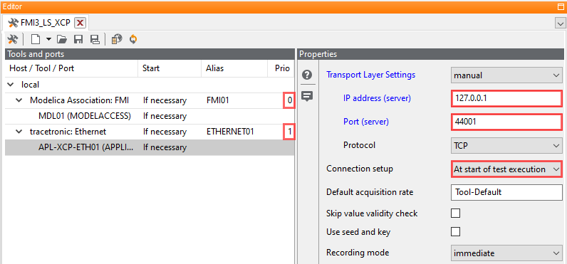
Test bench configuration:
- MODELACCESS-Port
Activate Automatic start/stop simulation
- APPLICATION-Port
For Connection setup select At start of test execution
- Priority
The MODELACCESS port must be started before the APPLICATION port and therefore have a lower Prio number. This ensures that the FMU is loaded first and the simulation is started before the APPLICATION port can access the XCP service, which is already running.
Info
The required values for the IP address (server) and Port (server) can be found in modelDescription.xml or fmi-ls-manifest.xml within the FMU.
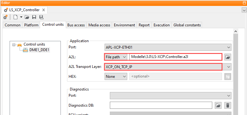
Test configuration:
- A2L file
In the tab Control units, select the A2L file that was previously extracted from the FMU in a manual step.
- A2L transport layer
Select XCP_ON_TCP_IP.
Properties 🛈
Name |
Available if |
Default value |
Valid values |
Type |
Description |
|---|---|---|---|---|---|
FMU Root Directory |
string |
Base directory for the FMU search. If it is a relative path specification, the base path of the tool host is used and extended by the directory specified here. |
|||
Automatically start/stop simulation |
☑ |
bool |
If this option is activated, the simulation will be started before the test run and stopped afterwards |
||
Change working directory |
do not change |
[do not change, temporary directory, individual] |
string |
Change of the working directory of the process which loads the FMU. By default, this remains unchanged on the ecu.test- installation directory. Optionally, it can be set automatically to the temporary directory where the FMUs are being unpacked (%TEMP%\ecu.test_FMI). A custom working directory is also possible. |
|
Custom working directory |
Change working directory: ‘individual’ |
string |
Working directory to which the FMU process should change, as an absolute path. The directory must already exist. |
||
Recording format |
MDF4 |
[MDF4, MAT, CSV] |
string |
File format for recording |
|
Timeout for tool call ❲in sec.❳ |
‘600’ |
string |
Timeout after which a tool call is aborted. |