Softing: DTS
Vendor information
Vendor |
Web page |
Product name |
Version |
|---|---|---|---|
Softing AG |
Diagnostic Tool Set |
9.01.008 |
Categories
MDL 🛈 |
APL 🛈 |
BAN 🛈 |
BMA 🛈 |
SVC 🛈 |
DGN 🛈 |
FIU 🛈 |
EES 🛈 |
FCT 🛈 |
DBG 🛈 |
IMG 🛈 |
AUDIO 🛈 |
ENVSIM 🛈 |
ENVCOM 🛈 |
|---|---|---|---|---|---|---|---|---|---|---|---|---|---|
✓ |
Data sources
File format |
Comment |
|---|---|
*.sod (Softing Venice database) |
|
*.odx (ASAM MCD-2D) |
indirect via import in DTS |
Platform
Operating system |
Support |
|---|---|
Windows |
✓ |
Linux |
Ports
Specifics
The API of DTS7 is based on ASAM MCD-3D standard.
DTS system concept (Softing): “DTS is composed of two large partial systems – the core system and the applications. The core system consisting of database and communication server allows a secure and tested control unit communication throughout the entire process chain – from development through testing and manufacturing right up to service. For every specific application there are the appropriate hardware interfaces. They allow accessing all established vehicle bus systems, such as CAN, LIN, FlexRay, MOST and K-Line. That core system can be used in proprietary applications, such as test systems or programming stations.” ecu.test is such a specific application for test automation.
Testbench options
Section name in “ToolLibs.ini”: [DTS7API]
Project: Here the project (already set up in DTS) is selected.
VIT: Here a VIT (vehicle information table) is selected.
Version: If several DTS versions are installed, it can be defined here which version should be used by ecu.test. If this field remains empty, the version will be started that has been stored as default in the registry (in most cases the last-installed one).
Port type DIAGNOSTIC
Provides a port for accessing the diagnostic interface.
Auto start: Should not be changed.
LogicalLink: <auto> selects at start a test configuration on the control unit tab. Otherwise a specific LogicalLink can be assigned here.
Port type BUSACCESS
Provides a port for bus access.
Auto start: Should not be changed.
Channel name: Name of the bus as set up in in DTS.
Bus type: Determines what kind of bus should be accessed (e.g. CAN, FlexRay).
Bus DB: <auto> selects at start the test configuration on the BUS tab; otherwise a specific bus database may be assigned here.
Port type FAILURESIM
Provides a port for access to Failure simulation Hard&Soft.
Auto start: Should not be changed.
Channel name: Name of the bus as set up in in DTS by means of which failure simulation is accessed.
To create a connection, DTS-Monaco has to be closed.
Further topics:
Setting up a sample simulation interface in DTS
In order to use the sample project in DTS (OBD) an interface has to be activated, easiest of all the simulation interface. To do so, start the file configurator.exe from the DTS program directory or choose at .
If alongside the simulation interface there are other active interfaces (recognizable by a red tick
in front of the name), those have to be deactivated first. For that purpose select the interface and remove
the tick at Enable interface on the right side.

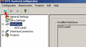
Now choose on the left side the item Interfaces and then click on the button N to arrange a new interface
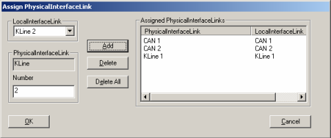
Now you have to enter the following information: Use the name “simulation” for both the long and the short name and select at interface simulated interface. Choose now assign PhysicalInterfaceLink … and add CAN1, CAN2 and Kline1 by means of the button Add. Confirm the dialog by OK.
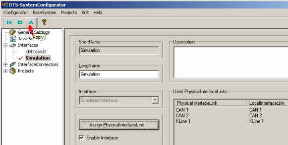
Now you must save everything by means of the button A save. When you have carried out everything a new interface by the name “simulation” and with a red tick ought to appear.
Setting up send CAN raw data for failure simulation
In order to control the failure simulation of Hard&Soft, a CAN connection is required. For accessing the CAN bus the D server is equipped with DTS-COS. For enabling DTS-COS to send raw data, a FIBEX link has to be established by means of DTS Venice. The simple creation of that FIBEX link is explained below:
In our example it is necessary, first of all, to set up a FIBEX project, here referred to as FIU_HuS.
Then a cluster is created (here: “CAN1Cluster”).
Now the settings Speed and PhysicalType have to be made as shown in the following illustration.
After, as shown in the next but one figure, the Channel has been established, it must be mentioned in the CAN1Cluster settings.

Configuring a channel consists of the following steps:
Setting up a new channel (“CAN1”) by means of the context menu of the Channel node.
Making the settings NmMode, NmBaseId as in the following figure
Establishing all frames (see next but one figure) and entering the frame triggers
Enter frame triggers
Right-click on FrameTriggerings
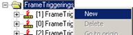
Select New and insert at IdentifierValue 0 for the first frame, 1 for the second, and so on.
Now select FrameRef and right-click on it in order to get Select in the context menu.
Choose in the following dialog RawFrame_0.
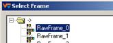
Create all 4 frame triggers as shown in the next figure

The configuration of the frames consists of the following steps:
Setting up a new frame by means of the context menu of the node Frames
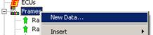
Enter RawFrame_0 for both short and long name
Data length is 8 Bytes
Repeat those steps to create RawFrame_1, RawFrame_2 and RawFrame_3
Switch back to channel “CAN1” and enter the frame triggers unless this has been done before.

After the FIBEX link is established, the whole database should be checked by hitting “F7”. Now the database is ready to use the Failure simulation Hard&Soft.
Failure simulation Hard&Soft
Hard&Soft failure simulation cannot be accessed directly. It is controlled by means of the CAN bus. At present, control is supported by the following software:
Failure simulation means that electric failures are created in a control unit. Normally those failures are displayed by entries in the failure control unit memory. Failures which can be simulated are:
an interrupted cable leading to a sensor/actor
a short circuit to ground or voltage
Failure simulation is established at test configuration where you have to indicate the configuration file included in the scope of supply.
Utilization in ecu.test is possible by means of the test step Electric failure simulation.
Properties 🛈
Name |
Available if |
Default value |
Valid values |
Type |
Description |
|---|---|---|---|---|---|
Project |
[ONLINE] |
string |
DTS project name |
||
VIT |
[ONLINE] |
string |
To project belonging vehicle information table |
||
Version |
‘<system default>’ |
string |
Using of specified minor version is forced. |
||
Automatic communication startup |
‘Without’ |
[‘Without’, ‘Connection setup’, ‘Connection and communication setup’] |
string |
‘GoToOnline’ and ‘StartCommunication’ will be started automatically on Package start. |
|
Timeout for tool call ❲in sec.❳ |
‘600’ |
string |
Timeout after which a tool call is aborted. |
Jobs 🛈
DisableApiTrace
EnableApiTrace
Parameterization
Parameter
Name |
Available if |
Default value |
Valid values |
Type |
Description |
|---|---|---|---|---|---|
Level |
int |
StartByteTrace
Parameterization
Parameter
Name |
Available if |
Default value |
Valid values |
Type |
Description |
|---|---|---|---|---|---|
Append |
False |
[False, True] |
bool |
||
FileName |
‘dtsByteTrace’ |
string |
|||
Limit |
2000000 |
int |
|||
MonitorLinkName |
‘CAN1’ |
[‘CAN1’, ‘CAN2’, ‘KLINE1’, ‘KLINE2’, ‘MOST1’, ‘J18501’] |
string |
StopAllByteTrace
StopByteTrace
Parameterization
Parameter
Name |
Available if |
Default value |
Valid values |
Type |
Description |
|---|---|---|---|---|---|
MonitorLinkName |
‘CAN1’ |
[‘CAN1’, ‘CAN2’, ‘KLINE1’, ‘KLINE2’, ‘MOST1’, ‘J18501’] |
string |