Failure simulation tab
The failure simulation tab contains all entries, which are configured on the platform tab of the currently loaded test configuration. These entries can be used to create test steps for electric failure simulation.
Electric failure simulation

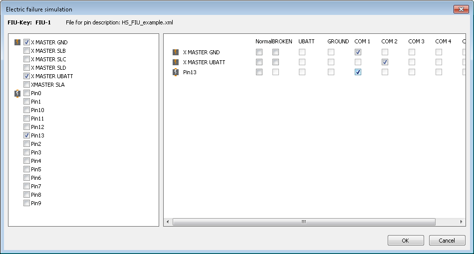
Inserting the test step Electric failure simulation opens the corresponding dialog window. This test step serves to control tools of the class Failure simulation.
By means of selection boxes on the left side the connections can be chosen on which a failure is to be simulated. The type of failure can be selected on the right side. The default value NORMAL will not produce a failure on the selected pins, BROKEN will create an interruption between ECU and the sensors/actors, COM1 and COM2 will close the line with an electrically conductive connection which by itself does not yet constitute a failure. For example, the connections “X master GND” and “pin13” can be put together on COM1 in order to connect “pin13” to ground.
The columns UBATT and GROUND have a special meaning: If the failure insertion unit has a fixed UBATT and/or GROUND rail, ticking the box will just connect the line to that rail. If however, such a fixed rail is missing, a free busbar (such as COM1 etc.) will be selected and the chosen line as well as the corresponding special line (for UBATT #1030, for GROUND #1031) will be connected to that busbar. The busbar as well as the special line then are no longer available for manual/explicit connections.
After confirmation with OK the test step will be inserted into the test case.
Note: Before the interface can be used it must be configured in the test configuration. Moreover, a mapping file should be specified which contains the association between symbolic pin names and the hardware.