Diagnostics tab
Info
Diagnostics can only be used with the Add-on ecu.test diagnostics
The Diagnostics tab offers symbolic access to the diagnostic functions of control units.
In order to use the tab, a test configuration with a diagnostic database must be loaded (see Control units tab). Depending on the format of the chosen database file, the diagnostic tab offers the test steps execute DIAG-SERVICE, read fault memory, DID read, DID write, execute IOControl and Routine Control. To get the best possible support from symbolic diagnostics, it is recommended to choose the standardized ODX format as the database.
If stepwise execution in simulation time is used, the test steps are designed in such a way that they continue the execution of the model each time they are executed.
Supported Database Formats
Open Diagnostic Data Exchange Format (ODX):
All diagnostic services, contained in the ODX- or PDX-file, will be offered as generic DIAG-SERVICE test steps that can be executed in a package. They are presented in a tree like structure, grouped by their respective service identifiers.
The diagnostic protocol (UDS/KWP2000) will be parsed from the database automatically.
To extract DTCs the additional test step Read fault memory is offered.
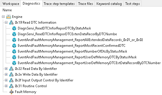
Global Diagnostic Data Export (GDX, MDX), CANdela Diagnostic Data (CDD):
Selected diagnostic services, included in the GDX-, MDX- or CDD-file, will be offered as specific test steps Read fault memory, Read DID, Write DID, IOControl and Routine Control for execution within a package.
The diagnostic protocol (UDS/KWP2000) will be parsed automatically from the database.
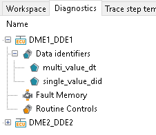
The first level nodes of the diagnostics tab correspond with the control units. A single control unit appears if it has a diagnostic database and a diagnostic port assigned in the test configuration. If no such control unit exists, the diagnostic tab remains empty.
Test step execute DIAG-SERVICE
This test step is a generic representation of the services, contained in a diagnostic database.
The test step can be added to a package via drag&drop or right click. In both cases the Execute dialog opens.
The parameters correspond with those of the request, the return values with those of the positive response.
For each return value, one of the representations BITS, TEXT or PHYS can be selected in the Values in column. For more information on the various representations, see the Representation section.
The response can be saved in the Save response dialog. The returned object is either a DiagServiceResult or a NegativeResponse.
An unexpected response or a timeout will lead to the test step being evaluated ERROR.
A negative response can be evaluated in the TAB Negative Response.

Test step read fault memory
The action Read fault memory calls the UDS (ISO 14229) service Read DTC Information (SID $19). The test step via the context menu (right mouse button) of the Fault Memory Node –> or by dragging it into the test case.
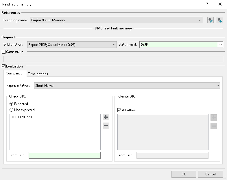
A new window Read fault memory will appear, where you can parameterize the test step. The Request area defines the subfunctions and, if necessary, the status mask. The status mask can be typed in directly, built by checking individual bits in the dropdown menu, or taken from a test case variable or another expression.
The result can be stored in a variable under the option Save value. Depending on the diagnostic response, the return value is one of the following types:
- api:
An object from the list DTCListDiagResult depending on the chosen subfunction
NegativeResponse object: Negative UDS Response (e.g. service not supported by ECU)
DiagResult object: Result after other errors (e.g. timeout)
Info
Unlike most other test steps, the Read fault memory test step stores a value in the variable even if the test step is rated ERROR.
With the Evaluation tab under the Comparison tab you have the possibility to check or to tolerate DTCs. Furthermore, the representation of the DTCs can be set.
The Check DTCs option provides a list for filtering expected or unexpected DTCs.
This can be done via the plus button in a search dialog as well as via the
From list option. In the From list text entry, you can
enter a Introduction in Python expression which may refer to the test case variables, and/or to
api.GlobalConstants. The expression’s evaluated value must be a list of DTCs. Each DTC in the
list may either be a string or number according to the chosen Representation or
a DTCAndStatusRecord object.
The latter allows you to re-use the DTCListDiagResult object
stored in a variable by an earlier call of this test step.
The Tolerate DTCs option handles all DTCs that should not be explicitly expected to be present/absent, but whose presence shall be tolerated. There is the option to tolerate all DTCs (check ) or to explicitly specify a list (just like under Check DTCs).
Time Options can be set under the according tab.
Test steps DID-read, DID-write and IOControl
Many DIDs can be read via the UDS (ISO 14229) service Read Data By Identifier (SID $22). For this, a special test step is used which has return values only. Writing, however, can be accomplished in various ways:
Some DIDs support Write Data By Identifier (SID $2E), which in ecu.test is done with a special test step which has input parameters only.
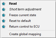
For other DIDs, Input/Output Control By Identifier (SID $2F) has to be used. In this case some or all of the modes , , and are available as test steps.
The parameters of the test steps can be specified as PHYS or TEXT. PHYS stands for integer or floating point values such as “42” or “3.14”. TEXT is used, for example, for ID or version numbers such as “‘XA05’” or for byte sequences such as those used when transmitting certificates or challenges during authentication, e.g. “ByteStream(‘0a:0b:0c’)”. The return values for byte sequences are also returned as TEXT as ByteStream.
In case of a target value can be specified; all modes sometimes accept a bit mask as their final parameter, which states that only a part of the data structure associated with the DID shall be affected. The current value is always additionally available as a return value.
When using Time Options with an expectation concerning the return value, Input/Output Control By Identifier (SID $2F) is called only initially, whereas for subsequent evaluations, the return value is obtained via Read Data By Identifier (SID $22).
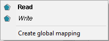
All mentioned test steps can be, as usual, created via the DID’s context menu or by dragging the DID into the test case. Further information about the read, write and execute dialog is available in the section Read / Write / Execute / Stimulus dialog.
Teststep execute Routine Control
The action Execute Routine Control calls the UDS (ISO 14229) Service Routine Control (SID $31). By dragging a routine control into the test case, the execute dialog opens. Further information can be found in the chapter Execute dialog. If the control unit does not respond or with a negative respond, the test step is evaluated with ERROR. The cause of the error is documented in the report.
Info
Results of the routine (subfunction 0x03, requestRoutineResults) can be waited for
with the time option wait-until-true. To support this case, the negative
response code (NRC) 0x24 (requestSequenceError) is converted to ~NotPresent~.
Complex Structures
To access elements of a structure, attribute notation can be used in a way that is similar to common programming languages. For elements of primitive data types, expectations can be formulated as usual.
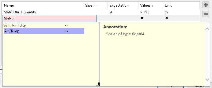
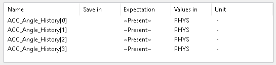
Individual elements of arrays can be accessed via their corresponding index, written in brackets.
ODX tables play a special role since tables are mapped in a special way in ODX. A table structure represents the actual desired parameterization but it does not have a statically unique type. The type is determined dynamically by the value of the referenced table key. Therefore, the auto-completion of the table structure parameter changes depending on the selection of the table key parameter.