Calibration tab

In the Calibration tab, variables that are connected via an application port can be both read and adjusted.
At the upper level the control devices are listed, the level below contains the corresponding adjustment
variables. Following the names of the control devices the corresponding *.a2l files are
indicated.
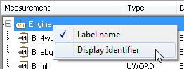
Through a right click on control devices a context menu opens which serves to set the variable name.
The background is as follows: variable names can be long descriptions of variables or references across
several layers. In order to display them, in spite of that, in a short and expressive way so-called
display identifiers are used. Variable names are assigned to the display identifiers in the
*.a2l file.
The context menu contains two options serving to switch between variable names and display identifiers. If a display is switched over, a corresponding remark is made in the configuration and at the next start that setting is reloaded.
A right click on a variable opens a context menu with the following actions:
- Read
If the option is chosen the basic dialog structure appears. The values shown with regard to Measured quantity, Type and Description serve only for information and cannot be modified. By means of the checkbox Save in it is possible to save read values in the current package for later use.
In the lower part of the tab there is the possibility to define an expectation for the value to be measured (or the values to be measured for characteristic curves and diagrams). The exact procedure is described in chapter Read / Write / Execute / Stimulus dialog.
If a value to be read is a matrix (vector, map) it is possible, besides the expectations for values, to assign expectations also to supporting points. Current values are shown in gray color and in brackets (if possible directly from the interface, otherwise from the
a2lfile). A right click opens a context menu to take over these default values as expectations or to delete registered values. A double click on a cell or a supporting value opens the familiar expectation dialog.Variables of type CURVE or MAP also have a running value that can be read by some tools.
- Write
If this option is chosen by Write a dialog appears whose structure is similar to that of Read. In that dialog it is possible to specify values to be written.
- Reset
Selecting the option Reset opens a dialog containing information about chosen units. If the test step is executed it resets the chosen unit to the value which was there before the test case was started.
- Create global mapping
Selecting this option in the context menu adds the variable path of the simulation model to the global mapping list. That can be done as well by “drag and drop” from the list of model variables. The meaning and use of mapping names is explained in the section Global mapping.
Furthermore, there is the possibility to insert calibration test steps without having to select a particular measuring unit. That can be looked up in the chapter generic.
Info
Depending on the type of variables specified in the calibration tab the section for reading or writing appears as a constant (VALUE), characteristic curve (CURVE, VAL_BLK) or characteristic diagram (MAP). The two latter are displayed as two-dimensional fields.
Info
Using the shortcut CTRL-F it is possible to search and show particular variables.
Supported Datatypes (Kinds)
The following Datatypes are supported by ecu.test:
CURVE
MAP
MATRIX
VALUE
VECTOR
Calibration objects of type AXIS are not shown as independent signals. They can only be accessed as components of the CURVE und MAP signals referencing the respective axis.