Electrical Error Simulation tab
On the EES error simulation tab all error simulation units from the test configuration, the so-called pins, are displayed. By using those pins test steps defining errors of the electrical error configuration can be inserted into the test case.
The test step Apply error can be inserted via drag and drop or via context menu into the test case and the dialog Error configuration will be opened. With the help of this test step tools of the category Failure simulation that are conform to the ASAM XIL API EES Port standard can be controled.
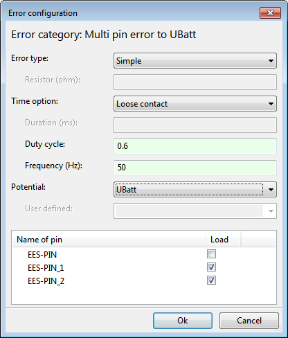
With the help of this dialog errors of various categories (see figure below) and all disturbance types can be created. The upper text shows which error category corresponds to the current configuration. The default configuration is a simple interrupt. The chosen pin will be added automatically to the dialog. Further pins can be added per drag and drop into the table in the lower part of the dialog. The pins will be automatically created as mapping items in the local mapping space. For every pin it can be decided whether it is under load (checked) or not (unchecked). If there are two errors configured, the error category changes to “Pin to pin” and with more pins to “Multi pin error”.
In the section of the error type a resistor (choose Resistor) can be specified. The according text field to insert the quantity will be activated.
There are three possible variants for the time option:
Static means a permanent error that is active as long as the error is applied.
Dynamic means a dynamic error that is only active for the given time span. The text field to insert the duration in milliseconds will be activated.
Loose contact simulates an intermittent error that is described by the duty cycle and the frequency.
By selecting a potential the circuit can be applied to ground, to battery voltage (UBatt) or to a user defined potential.
After submitting the dialog with OK the test step will be added into the test case. In the background an ErrorSet with exactly this one error will be created. If more than one error should be applied at the same time, they have to be added explicitly to an ErrorSet. This test step can be found on the Test steps tab in the folder Default test steps > Tool access and is named EES ErrorSet. With this test step it is also possible to add errors to an already applied ErrorSet.
Note: First the interface for the creation of electrical errors has to be configured in the test configuration. Furthermore a mapping file is specified which contains the correlation between symbolic pin names and the hardware.
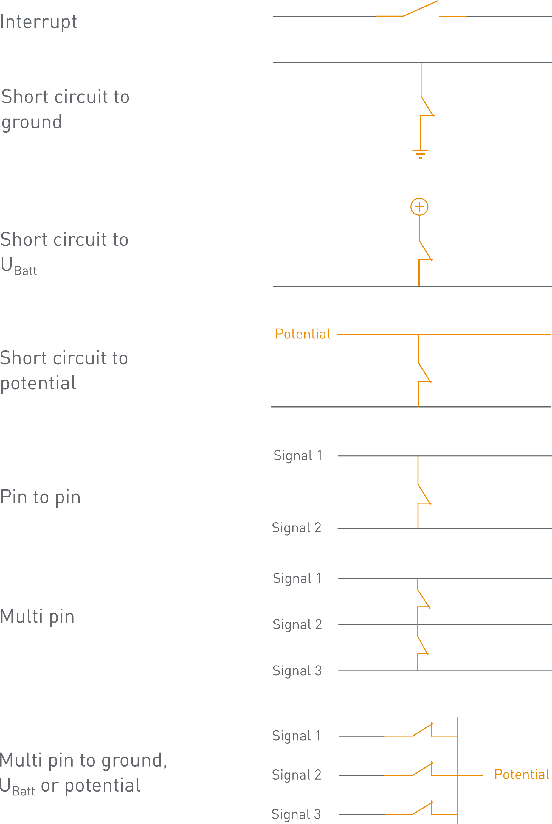
The parameterization determines the error category that will be applied. The following error categories are possible: