Bus access tab
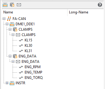
The Bus access tab contains all bus systems which can be accessed by ecu.test. The different buses
carry the bus symbol  .
.
Every bus system is separated into frames ( ) which exist on the bus in question.
The frames, in turn, are divided into PDUs (
) which exist on the bus in question.
The frames, in turn, are divided into PDUs ( ) and signals (
 ). What
frames, PDUs and signals exist is specified in the bus access file (
). What
frames, PDUs and signals exist is specified in the bus access file (dbc, xml).
Supported PDU types are I-Signal-I-PDU, Multiplexed-I-PDU ( ),
Container-I-PDU, Secured-PDU (
),
Container-I-PDU, Secured-PDU ( ). In addition to the PDU contained in the
Secured-PDU, the so-called Authentic-I-PDU, ecu.test provides the signals _authInfo
and _freshness that contain the information about “Authenticator” and “Freshness Value”.
). In addition to the PDU contained in the
Secured-PDU, the so-called Authentic-I-PDU, ecu.test provides the signals _authInfo
and _freshness that contain the information about “Authenticator” and “Freshness Value”.
This listing of frames, PDUs and signals can be filtered using the three buttons in the header. Filter options are:
Nodes

Frames
PDUs
Info
Hiding the nodes has no effect on the paths of already existing Mappings.
Following possible actions for frames, PDUs and signals are explained.
Info
By using the shortcut CTRL+F it is possible to search and show particular frames, PDUs or signals.
Info
In the pre-process of every package the bus tool is informed what frames/PDUs/signals are to be received. Only after that can reception begin, so that right at the beginning of a test certain frames may not have been received yet. It may be necessary to insert a waiting step here.
Frames
A right click on a frame shows the following context menu:
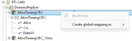
Create global mapping
If this option is selected in the context menu the variable path of the simulation model of the global mapping list is added. The names of variables may also be added taking them by drag and drop from the list of model variables. The meaning and use of mapping names is explained in section global mapping.
PDUs
A right click on a PDU shows the following context menu:

Signal group read/write/write cyclic
This opens a dialog in which the mapping name is shown in the upper part. After confirmation by OK a function block is inserted into the package that contains all signals of the PDU selected, in the IN block (write PDU) and in the OUT block (read PDU). The signals can now be edited individually and be compared with expectations, or the values to be written can be defined. If WriteCyclic is chosen, the bus parameters CycleTime and CycleCount are included additionally. They determine the period duration in milliseconds as well as the number of PDUs to be sent. If the CycleCount is set to 0 the signal group is sent continuously in the specified cycle time. The sending can be stopped if the CycleTime is set to 0, too.
Change PDU timing
This option creates a test step to determine if a PDU is to be sent or not. For this it is necessary that the used port supports manipulation. On activating a PDU the cycle time for the PDU can be specified.
Moreover, a frame calculation class can be used to specify the signal values.
Additionally, the cycle time and frame calculation class of an activated PDU can be modified without restarting the cycle. For this purpose the state of activation must not be altered.
For LIN-PDUs the cycle time is used to control the master request. Set it to 0 in order to deactivate the master request. The state of activation determines whether slave responses are sent.
Reset PDU timing
This option resets the timing of a selected PDU. For this it is necessary that the used port is a generic bus port.
Create calculation classes
By clicking on the context menu Create calculation classes, a basic framework for this class is created automatically. You can find out from the template how the implementation has to be carried out. For more information, see Mini residual bus simulation.
Clear buffers for frame and signals
This option creates a test step to clear the receive buffers for the frame (-> read signal group) and the individual signals (-> read signal). This causes the value of all affected signals to be ~NotPresent~ until the next reception of a frame containing the respective signal. Clearing the receive buffers is supported only by the close-to-hardware bus connections (whose name ends with -HW).
Create global mapping
If this option is selected in the context menu the variable path of the simulation model of the global mapping list is added. The names of variables may also be added taking them by drag and drop from the list of model variables. The meaning and use of mapping names is explained in section global mapping.
Signals
A right click on a signal opens the following context menu:
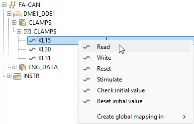
Read
If the option is chosen the basic dialog structure appears. The values shown in the sectors measured, type and description serve only for information and cannot be modified. When signals are read a distinction is made between returning a physical and a raw value. The return of a physical value is preselected. As an alternative the check box ‘use raw value’ can be chosen in signal mapping (Local mapping). The correct byte order and signal typification will be used for that value. By contrast, with a physical value the conversion function of the signal and the indicated unit will be used in addition. It is possible, by means of the checkbox Save in, to save the read value in the current package for later use.
In the lower part of the tab an expectation can be defined for the value to be measured. The exact procedure is described in chapter Read / Write / Execute / Stimulus dialog.
Write
If the option Write is chosen a dialog appears which in its structure is similar to the dialog Read. In that dialog it is possible to specify a value to be written.
Reset
This option resets a manipulation carried out with the step Write.
Check initial value
This option returns the first value received of a signal.
Reset initial value
This option resets the first value received of a signal. Thus it can be checked whether or not a signal is being received.
Create global mapping
This option in the context menu adds the variable path of the simulation model to the global mapping list. Names of variables may also be added taking them by drag and drop from the list of model variables.
The meaning and use of mapping names is explained in section Global mapping.