Read / Write / Execute / Stimulus dialog
This chapter describes general functions which can be used in several tabs of an action window.
Note: If rational numbers (fractional numbers, numbers with decimal places) are inserted, it must be taken into consideration that instead of a comma a point has to be used as decimal separator. So the number 4,2 has to be entered as 4.2.
Read dialog
If a value is read, for example, from a control device, a model etc. ecu.test provides the possibility to compare the read value with an expectation. That expectation can be specified when a test step is inserted into a package. A separate part of the dialog serves to determine the expectation.
The following figure shows a read dialog which appears when reading values from the Measurement tab. Only the upper section differs in part from other dialogs.

In the first step a mapping name has to be determined. ecu.test already provides a suggestion which can be used. The selection list shows all further mapping names (if any) that refer to the same element. The button on the right serves to change the name, determine additional options (e.g. use raw value) or create a new mapping.
The data below marked in gray serve for information and can be modified in mapping properties. In case the variable contains, manually defined or from the description file, enumeration information the corresponding button enables to view such information.
If the indicated representation is not available for a reading test step a “NoRepresentation” object is returned. For test cases established before ecu.test version 5.2 the compatibility representation may be pre-set. If that is not the case the user should select the required representation subsequently, as otherwise the representation would be automatically determined by ecu.test.
In the field Unit the unit of measurement can be determined into which the measured value is to be converted. Here, by default, the unit of the test value has been chosen that is specified in the database in question and also shown in the above mapping properties marked in gray.
Next follows a field for optional specification of a test case variable in which the read value is to be saved for use in subsequent test steps.
Below that follows the expectation section. By ticking or not ticking the checkbox Evaluation, one can select whether the read result shall be evaluated or not. If there is to be an evaluation, an expected value has to be specified. That is done by means of two tabs, Comparison and Time options. These two are largely consistent with the tabs Expectation and the section Time option of the tab Options found in the Calculation test step. Therefore here only the differences are explained.
Write dialog
The Write dialog is visually similar to the Read dialog. However instead of an expectation there is a value that is to be written to the test variable. The following figure shows a write dialog as it appears when writing values from the Calibration tab.

In the selection list Representation as well as Unit the type of value or its unit can be specified. A unit can only be selected if it is specified as the representation physical conversion has been selected. The default values result from the values specified in the data basis for the parameter.
The value is entered in the lowest field. This can be entered directly as a value, variable or as a Python expression that can reference test case variables. If text representations are specified in the database, they are displayed as a list option.
Execute dialog
A function call can be parameterized with the execute dialog. The following figure shows a execute dialog for starting a Routine Control from the Diagnostics tab.

The field Parameter consists of a table with all parameters taken from the database. The table consists of the columns Name, Value, Values in and Unit. In the last three columns, the value, and at leaf nodes the representation and the unit can be entered in the same way as in the write dialog.
If the call has return values, these are displayed in the table Return values. Each return value contains information about the Name and can be stored under Save in in a variable. In addition, an Expectation can be made by clicking in the corresponding cell. In this case, an expectation dialog opens which is similar to the tab Expectation. Furthermore, under Values in and Unit, the representation or the unit of leaf nodes can be chosen. The test step is only performed with SUCCESS, if all expectations are fulfilled.
It is possible to add and remove parameters and return values. This is useful especially with Service test steps to read and write substructures. Generally, all parameters and return values can be complex structures, which can be navigated through via dot notation.

With suitable service test steps, in addition to the individual return values, the packet as a whole can also be evaluated.
In the lowest field the time options can be specified, which are explained in the section Time options in more detail. This option is only available if at least one expectation has been made.
Special options
Representation
The selection list Representation serves to determine the type of return value for reading test steps, and the type of argument for writing test steps. The following types are available:
- Bitcode
Here a value is represented by data type BitStream. This representation corresponds to the data bit stream as sent at the lowest level of the transmission medium. It is particularly relevant for BUS operations.
- Raw value
A raw value is, as a rule, a numeric value for whose creation byte order and data type are considered.
- Interpreted text
Here the textual representation of a value is used.
- Physical conversion
The value of this representation stands for a raw value to which a conversion formula has been applied as stored, for example, in a bus database. If no conversion is available the physical value corresponds to the raw value.
Comparison tab
In this tab you specify the Expectation regarding the read value. Unlike the calculation test step, the read value need not be a single, scalar value, but might (depending on the chosen test value) rather be a vector, a matrix, a characteristic curve or a characteristic diagram.
For those data structures one can either specify distinct expectations for single elements. For that purpose one selects the option Single for Type, specifies the correct dimension(s) near the left margin and opens the expectation dialog for the desired table cells via a single click, or, in case of the supporting points of characteristic curves or diagrams, by double clicking.
Alternatively, one can enter just one expectation, which has to be fulfilled by every element. To achieve this, one must choose Common for Type and click Edit to open the expectation dialog. For characteristic curves and diagrams, only the inner entries are compared to that expression, not the supporting points.
Time options tab
Here a time option can be specified. Instead of continuously reevaluating an expression the referenced test quantity is continuously read.
Ignore Response
This option causes not to wait for the return value, but only to write the test case variable or call the function.
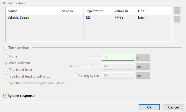
This is interesting e.g. with SOME/IP methods to be able to send a REQUEST without having to wait for the RESPONSE. Return values are accordingly not possible with this option. This is to be distinguished thus from an asynchronous execution, since among other things no Future object is returned, in order to be able to access afterwards the return value.
Stimulus dialog
A variant of playing a stimulus on a signal is the stimulus test step that is described here. (Tools with stimulus support)
Stimulus definition
Instead of referencing an STI file, the stimulus is definied by one or multiple segments directly in the test step dialog. Segments are added using the + button. Existing entries can be edited by double-clicking them.
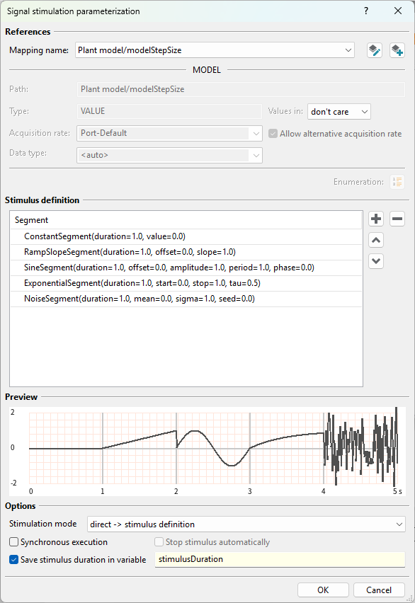
The available signal segments are described here.
The signal segments are parameterized with numerical values, global constants or test case variables.
Options
The defined stimulus can be played back on the mapping target in three different ways. With the direct mode, the stimulus is played back on the mapping target as defined. With the modes add and multiply the current value of the mapping target is added or multiplied with the defined stimulus and the result is played back on the mapping target.
Info
The stimulation modes add and multiply can only be used for XIL tools. The XIL server must support stimulation with input signals.
There are two modes of execution:
- Asynchronous execution
The test execution continues immediately after the stimulus is started and there is no waiting until the stimulus has been played back completely. This is the default behavior.
- Synchronous execution
The test case execution is paused until the stimulus has been completely played back. This execution mode is activated via the Synchronous execution checkbox.
If Synchronous execution is activated, the option Stop stimulus automatically can also be selected. If activated, the stimulus will be implicitly stopped automatically as soon as it has been played completely. An additional Stop Stimulus test step in the further course of the test case is not required.
It is possible to save the duration of the stimulus in a test case variable and then use this in the test case e.g. in a Wait test step.
Info
The behavior of an asynchronously executed stimulus test step with an immediately following Wait test step, which was parameterized with the stimulus duration stored in a test case variable, is identical to that of a synchronously executed stimulus test step.
Restrictions
The following restrictions apply when using the stimulus test step (especially in contrast to the Start Stimulus and Stop Stimulus workflow).
Only a single signal can be stimulated per stimulus test step
The following segments and operations are not supported:
Info
For the tool connection to MATLAB & Simulink, only the interpolation type backward is supported for the DataFile Segment segment.