Stimulation control
This category contains the test steps Start Stimulus and Stop Stimulus which control the running of a stimulus.
An alternative to playing a stimulus is the test step Signal-Stimulation (short: Stimulus test step).
While in the stimulus test step the signal shape is defined directly in the test case and only a single target variable can be stimulated, the Start Stimulus test step offers the following possibilities:
Use of STI and STZ files according to ASAM XIL standard.
Direct use of other data file types like CSV, MAT, MDF4 etc.
Assignment of input signals (StringSymbol as segment property and Alias in stop trigger expressions according to ASAM standard) and parameters, as long as they are defined in the used STI/STZ file.
Signals from the file to be stimulated can be assigned to several target variables.
Restrictions and special features
The mentioned possibilities of stimulation are not available for all tools with stimulation support. This is due to the fact that the actual playback of the stimulus is the responsibility of the tool in use. ecu.test only passes the data to be stimulated to the tool. However, ecu.test also tries to prepare the data to be stimulated according to the specific tool requirements:
For tools that can only stimulate with CSV, the specified data file is automatically converted to a CSV (e.g. Silver, VeriStand). Therefore, in the Start Stimulus test step any file type can be specified.
If a tool supports stimulation natively with a certain file format, then this file is sent to the tool without modification for stimulation.
If a tool supports the STZ format and a data file is specified (e.g. MAT), then a temporary STZ file is implicitly created. The STZ file contains one signal per signal used by the test step with a DataFileSegment referencing the data file. In this case, it is important to ensure that the data file used is supported by the respective tool, as ecu.test cannot convert the referenced files into a tool-compatible format for all Tools with stimulus support. See Overview of the stimulus capabilities of the tools for more information.
With most tools, ecu.test completely takes care of the tool-compatible preparation of the stimulus data. It is therefore possible to use any input data format as long as ecu.test is able to read it.
In general, it is useful to find out which signal stimulation capabilities the used tool offers. This information can be found in the manual of the respective tool or by contacting the tool manufacturer. Especially with the ASAM XIL STI format, it can happen that only certain versions (1.0, 2.0, 2.1, 2.2, etc.) are supported, or that not all defined stimulus segment types are allowed.
Another special feature is STI files with externally referenced data files (as DataFileSegment or as SignalValueSegment). In particular, when using Tool Server, where the tool is running on a different computer, it has to be noted that for stimulation the relevant files must be transferred from ecu.test to the target computer. However, it can not always be ensured that the referenced files are also transferred. In addition, the files on the target computer are inevitably located in other file system paths (in the ToolLibTemp directory). Some tools also have special requirements on how the referenced files are specified in the STI file (with absolute or relative path).
To prevent such problems, it is recommended to use the STZ format. This is a simple ZIP file (with .stz extension), into which the referenced files can be packed.
Start Stimulus
This test step starts the playback of a stimuli from a file which contains a signal curve. The supported file formats depend on the selected tool. Typically stimuli files (.sti) or compressed stimulus files (.stz) are supported. ecu.test ships the Signal Editor which may be used to create or edit such files. Besides the use of .sti/.stz files, also all trace formats readable by ecu.test can be used directly for stimulation.
ecu.test creates an STI file at execution time and includes the selected signals of the specified trace file as data file segments. ecu.test converts the specified trace file into a tool-compatible format by default (with the exception of some tools/ports, see Overview of the stimulus capabilities of the tools). The trace files referenced in an STI file in the DataFileSegment are also automatically converted into a tool-compatible format.
If you add the test step, the following dialog window opens:
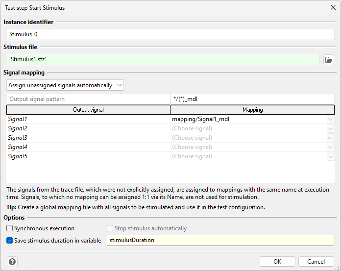
The stimulus file is shown in the field Stimulus file. Instead of entering the file name as text you may also choose a file in the familiar opening dialog by means of the Open button. File paths may be absolute or relative to the current workspace.
Info
The stimulus file can also be parameterized via a test case variable. During test execution, the stimulus is then updated at runtime. Depending on the tool used, there may be a delay in setting the new stimulus. Therefore, it is recommended not to change the stimulus file compared to the file at the start of the package.
Signal assignment
Stimulation is port-based, so it is not permitted to assign mappings of different ports to a Start Stimulus test step. If test quantities are to be stimulated on different ports, a separate Start Stimulus test step (and, if necessary, a corresponding Stop Stimulus test step) must be configured for each port in the test case.
It is allowed to use the same stimulus file for multiple Start Stimulus test steps.
Output signals
The table Signal mapping shows in the left column all the stimuli contained in the stimulus file called up last. In the right column you can choose signal mappings on which the stimulus concerned should be run. A stimulus may be assigned several signal mappings, but each signal mapping may be assigned to one stimulus only.
Info
The start and stop of the stimulation is port-based and subject to port/tool-specific latencies. For this reason, when using the execution modes continuous and real-time (see Temporal behaviour), it cannot be expected that the stimulations of the different Start Stimulus test steps will run synchronously.
The drop-down list can be used to switch between three modes of signal assignment. By default Manually assign signals is selected. With Automatically assign signals the signals are assigned 1:1 to the loaded mappings at test execution time based on their names. Likewise with Assign unassigned signals automatically a mixed mode is possible, where only those signals are considered for automatic assignment, which have not already been assigned manually in the signal assignment table.
The (partially) automatic signal assignment can be advantageous if many signals from a measurement file are to be stimulated in several test cases. Then you can simply use a global mapping for the signals to be stimulated and load it with the test configuration. In all test cases in which the Start Stimulus test step with (partially) automatic signal assignment is used, all signals for which a unique 1:1 mapping of the signal is available are stimulated at test execution time.
When in mode Automatically assign signals or Assign unassigned signals automatically it is possible to specify matching patterns, in case a unique 1:1 mapping of the names is not possible. This is useful if, for example, the signals have some prefix with regard to the mapping names.
Example for using patterns
The output signal recording/10ms/velocity is to be assigned to mapping velocity [m/s].
The following patterns may be used:
Output signal pattern:
recording/*/(*)Mapping pattern:
(*) [*
The partial strings that are determined in between the round brackets are extracted from the identifiers and used for the comparison.
Pattern syntax
Each pattern must contain exactly one pair of round brackets to define the substring of interest for the comparison. The following special characters are supported:
* … Wildcard for any string
? … Wildcard for any character
For the signal assignment only signals or mappings are considered, to which the respective pattern is applicable. The pattern must match the identifier from the first to the last character.
Info
In the Automatically assign signals mode the check whether the test step can be executed without errors is limited. This is due to the fact that a different stimulus file could potentially be present at runtime compared to the one during test case editing. However, the dynamic signal assignment always refers to the stimulus file at the time of execution.
Furthermore, it depends on the tool used, whether at runtime other target variables can be stimulated than those, which were already known at the beginning of the package execution. This must be checked in each individual case.
Input signals
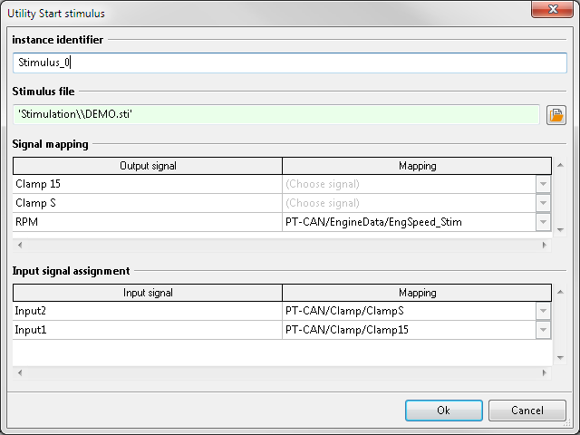
If the selected stimulus file contains input signal definitions (e.g. as StringSymbol for a segment property or as an Alias within a stop trigger expression), using this test step these signals can be mapped as well.
Info
The ASAM standard allows Alias and StringSymbol to have identical names. In this case, only one single mapping can be assigned to both the StringSymbol input signal and the Alias input signal. If it is necessary to assign different mappings to these input signals, the Alias input signals and StringSymbol input signals must be clearly distinguishable from each other.
Options
There are two modes of execution:
- Asynchronous execution
The test execution continues immediately after the stimulus is started and there is no waiting until the stimulus has been played back completely. This is the default behavior.
- Synchronous execution
The test case execution is paused until the stimulus has been completely played back. This execution mode is activated via the Synchronous execution checkbox.
If Synchronous execution is activated, the option Stop stimulus automatically can also be selected. If activated, the stimulus will be implicitly stopped automatically as soon as it has been played completely. An additional Stop Stimulus test step in the further course of the test case is not required.
It is possible to assign the determined duration of the stimulus to a test case variable and then use this value in the test case e.g. in a Wait test step. When determining the duration, only the actually assigned signals of the stimulus file are taken into account.
Stop Stimulus
This test step terminates the use of stimuli from a stimulus file.
Attribution to the corresponding Start Stimulus is made via an instance identifier; this is why you have to choose the same instance identifier which had already been chosen in Start Stimulus.