Lesson 3: Test case with system access
In this lesson, you create a test case that no longer performs only local calculations, but accesses the system via the loaded configurations. This combines what you learned in Lesson 1 and Lesson 2 into a first realistic test case in the editor.
At the end of this exercise, a test case writes a model quantity, gives the system time to react, and then checks whether the expected state has been reached.
Prerequisites:
Lesson 2 is completed.
The configurations were created, selected, and started as described in Creating a new test bench configuration using the test bench configuration editor and the test configuration editor.
The Model Access tab is available in ecu.test.
Test case specification
In this example, you first implement the following basic test case:
- Action:
Set the driver request to 50 %
Wait 10 s
- Check postcondition:
Vehicle speed is above 80 km/h
The example follows the action-reaction pattern Write –> Wait –> Read. First an input value is written, then the system gets time to react, and finally the resulting state is checked.
Create a package
As in Lesson 1, the test case is created in a new package.
Create a new package: .
In the editor, an empty package opens and will be filled with test steps in the following steps.
Save the package using one of the following options:
in the menu
Save package button
Keyboard shortcut Ctrl+S
The file explorer opens in the
Packagesdirectory of the configured workspace.Enter a name, for example
EV_Test.Confirm with Save.
Info
A package does not have to be saved before execution. However, it is recommended to save intermediate results regularly.
Create the write test step
Since the configurations were started, the system model quantities are available in the Model Access tab. From there, they can be inserted directly as test steps.
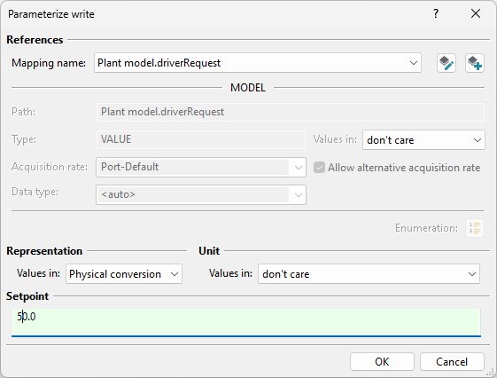
You put the system into a defined state by setting the model quantity driverRequest to
50. This corresponds to a pedal position of 50 %.
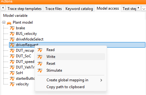
Open the Model Access tab and expand the root node.
Right-click driverRequest and select Write.
Enter
50as the Setpoint and confirm with OK.
The package now contains a write test step that writes the value 50 to the model
quantity driverRequest. In other words, the vehicle is expected to accelerate with a
50 % pedal position.
Insert the wait test step
To give the vehicle, that is the system under test (SuT), time to accelerate, you insert a Wait test step after the write step.
Without this waiting time, the next test step would be executed immediately after writing the new value. The system would have no time to react.
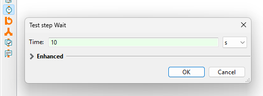
Insert a Wait test step using the toolbar on the left side of the package editor.
Enter
10sas the Time and confirm with OK.
There is now a reaction time of 10 seconds between the write step and the later check in the test case.
Create the read test step
After the waiting time, you check whether the expected state has been reached in the system and whether the vehicle has accelerated to the expected speed. To do this, read the model quantity velocity and compare it with your expectation.
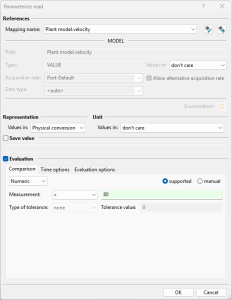
In the Model Access tab, right-click velocity and select Read.
Enter the expression
> 80as the expectation in Measured value and confirm with OK.
The package now contains a read test step that compares the current value of velocity
with the expectation > 80. The test case is now complete: Write –> Wait –> Read.
Execute the test case and evaluate the result in the report
Now execute the complete test case and evaluate the result in the report.
Press F9 or click Run test case in the package editor.
The test case is executed. The test result is shown in the Test report tab.
If the configurations are loaded correctly and the system reacts as expected, the read test step is rated SUCCESS and the vehicle has accelerated to more than 80 km/h.
In the report, the sequence of the test case becomes visible: the write test step stimulates the system, the wait test step gives it time to react, and the read test step checks the resulting state. The evaluation therefore shows directly whether the expected behavior has occurred.
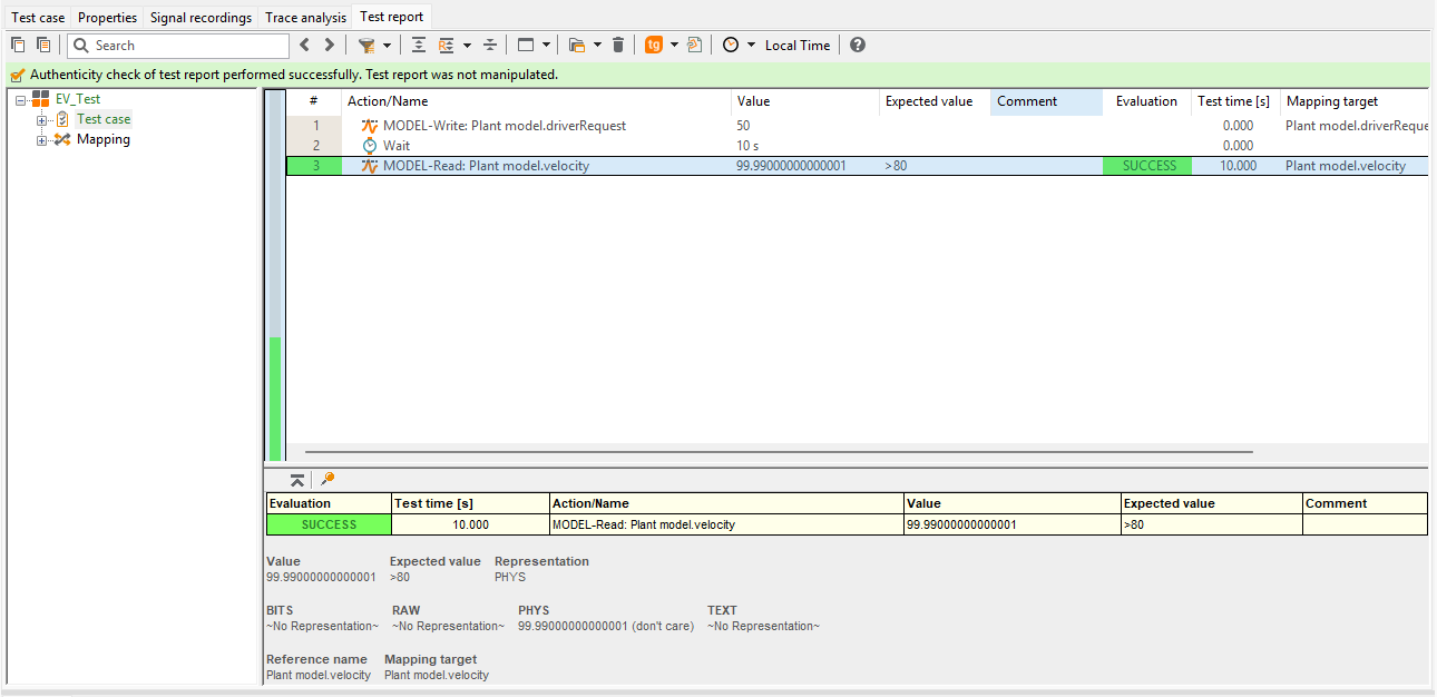
Result of lesson 3
You have created a test case with system access: a model quantity from the Model Access tab was inserted into the package, a value was written, a waiting time was added, and the resulting system state was checked.
This pattern Write –> Wait –> Read is the basis for many test cases in ecu.test. It can be extended to more advanced scenarios with multiple tools or ports, additional signals, and further checks.
In the next lessons, you build on this foundation, for example with mappings between test quantities and model signals as well as with signal recording and trace analysis over longer periods.
Continue with Lesson 4.