General approach
In ecu.test, the following specification types for trace step templates are available. Trace steps of these types can be combined in a trace analysis.
In general, trace step templates are treated as files in directories whose contents are shown in the Explorer view (left) in the tab Trace step templates. The categories My templates and Default templates are offered. The directory contained in My templates can be modified at . In ecu.test any kind of sub-folders can be created within that directory to group trace step templates (see Figure Creating a (sub)folder in the trace step template directory).
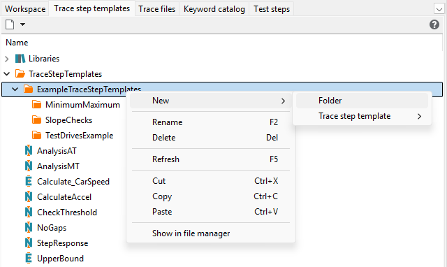
Creating a (sub)folder in the trace step template directory
New trace step templates can be created by clicking the button New trace step template. When choosing Python event-based or Python stream-based, the dialog for editing trace step templates will be opened.
That dialog comprises the four sections
Common,
Signals,
Parameter and
Analysis instruction.
When choosing NumPy array-based, a similar dialog is shown, which actually is a wizard. After filling it in and clicking Generate, a Python source file is generated and opened, such that the actual analysis instructions can be implemented there.
When creating Timing diagrams another dialog is shown that has several panels: the toolboxes Element properties, Parameters and Assignments, and the actual workspace for modelling a timing diagram as analysis instruction. The timing diagram editor is explained in detail in timing diagram manual and is therefore not covered by the following sections.
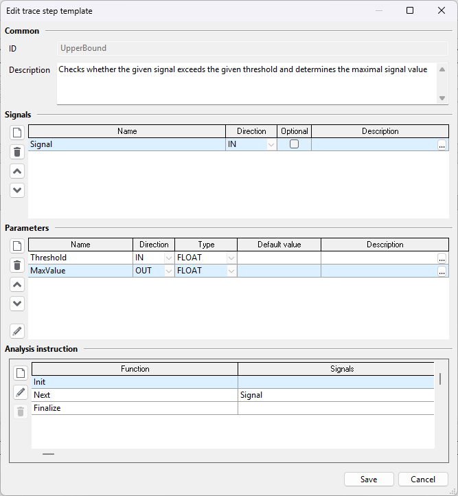
Editing a (python event-based) trace step template
- Description
The Description can be used to document the general functionality of the trace step template.
Info
If no specific description is given when using this trace step template, the first paragraph (the text up to the first empty line) will be displayed in the report.
- Signals
Signals serves to define the signals which should be used in the trace step template. Signal names in the first column can be freely chosen and should be as self-explanatory as possible.
In the second column each signal is specified as incoming (IN), i.e. it can later be assigned an existing signal and is eligible only for reading treatment, or as outgoing (OUT), i.e. it will be created by using the method dataContainer.EmitSignal and can then be addressed by its name and continue to be used by following trace step templates (see also Section Signal processing with trace steps).
In the third column a signal can be marked as Optional by a tick in the option box. That column is relevant for incoming signals only. In that case it is not imperative to assign a generic signal to it for later use. So the trace step template can be made more flexible, and unnecessary creation of many similar trace step templates can be avoided if, for example, some signals are not available in some of many similar applications.
Info
If the user later decides to use such an optional signal, then he must assign a fully working generic signal. ecu.test will report error (ERROR report entry) in case something is wrong with the assigned signal. Possible problems are broken mappings or a forgotten signal binding in the sector Signal connection of the trace analysis.
However, the user has the possibility to mark the specific signal binding as optionally present. This indicates ecu.test explicitly, that (depending of the configuration or the recording) there can be problems resolving the mapping or searching the signal in the trace (e.g. if the signal is not measured for a specific test bench). If the option is set, the trace analysis will start although there is a problem with the signal. It will handle the signal like it has no samples.
The fourth column is reserved for an optional description of a signal. A click on the ellipsis opens a dialog in which the textual description can be entered.
Info
The concrete signal need not (and cannot) be determined at this place. A connection with generic signals is not made until the actual use of the trace step template later on.
- Parameters
The part Parameters serves to make the trace step template as reusable as possible. It allows defining parameters which will assign the trace step template concrete values in later utilization. The parameter section is also divided into five columns.
Parameter names in the first column can be chosen freely.
In the second column each parameter is specified as incoming (IN), i.e. it can later be assigned with a value or package variable, or outgoing (OUT), i.e. a value is assigned when executing the trace step template, that can be assigned to a package variable.
These values can be valid Python terms, which in particular can contain names of variables (from the Variables tab). Any valid Python terms can be used for value assignment during the subsequent parameterization of the trace step template. Therefore the type of a parameter, which can be chosen as “INTEGER”, “FLOAT”, “STRING”, “BOOLEAN” or “PYOBJECT” in the third column, serves solely for the formulation of expectations of the template creator.
The fourth column Default value can be used to define an optional default for incoming parameters. The input control of that column depends on the selected parameter type. An empty value means that no default is configured.
When the template is used, this default is only applied if the parameter value assignment is empty (“None”).
Like signals parameters can also get a description in the last column.
- Analytical instruction
The purpose of defining signals and parameters is to use the defined names within the implementation of the trace step templates (Analytical instruction). How this works for the different template types is described in the following sections.